7
EXAMPLE CONFIGURATIONS
This section demonstrates the flexibility and utility of the LD-
2 with four sample applications.
LOUDSPEAKER PLACEMENT AND POLARITY
The loudspeakers in the following configurations are in a
close-proximity coplanar orientation, unless otherwise stated.
In general practice, placing adjacent loudspeakers more than 5
feet apart may require setting them to opposite polarities to
compensate for the propagation delay between these
loudspeakers.
MEASUREMENT AND CORRECTION
Measurement and correction tools are required to optimize any
professional sound system. This is all the more necessary and
complicated for applications requiring large numbers of
loudspeakers, loudspeakers in complex acoustic spaces (in
which there will be multiple interactions between the
loudspeakers and the architectural/acoustic surfaces) and/or
when multiple loudspeaker positions or zones are required.
We recommend using the Meyer SIM System II Sound
Analyzer and CP-10 Parametric Equalizers to assist in the
process of choosing and configuring loudspeaker positions.
SIM-II is perfectly suited to measure propagation delays
between subsystems, to set the correct polarity and signal
delay, to measure and to equalize the frequency response
resulting from the acoustical environment and the interaction
between loudspeakers. Contact Meyer Sound for assistance
with your application.
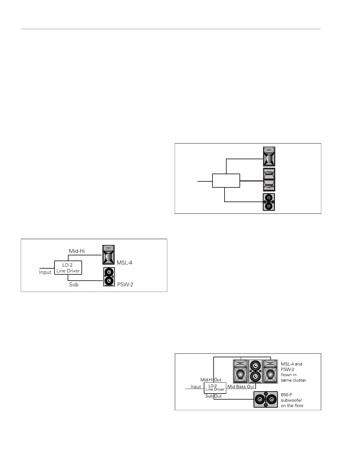
MSL-4 AND PSW-2
The MSL-4 and PSW-2 form a compatible full-range system.
However, due to an overlap in the low frequency range
between the two adjacent loudspeakers there will be increased
acoustic output over the 65-120Hz frequency range when
these loudspeakers are combined. Note that the loudspeakers
are in phase in this region. The combined frequency response
may be optimized by activating the Lo Cut filter on the Mid-
Hi output of the LD-2. Ensure that the polarity switches for
the output channels feeding the MSL-4 and PSW-2
loudspeakers are not inverted. In most applications, the ratio
of MSL-4's to PSW-2's is 2:1, but the Sub and Mid-Hi gain
controls in the LD-2 allow for variations in this ratio while
maintaining the spectral balance of the system. The 650-P
may be used interchangeably with the PSW-2 but the 650-P's
larger size does preclude tight-packing configurations with the
MSL-4. The 650-P also lacks rigging hardware.
MSL-4, DS-2P/DS-4P, AND 650-P
Adding the DS-2P or a DS-4P to an MSL-4/650-P system
enhances LF power and clarity. With the Mid-Bass or AUX and
Sub Crossover switches in, the Mid-Bass and Sub outputs are
sent signals optimized for the frequency response capabilities
of the DS-2P/4P and 650-P.
The MSL-4 is driven from the Mid-Hi output with the Lo Cut
filter switched in for the purpose of minimizing overlap that
would otherwise alter the frequency response when combined
with the DS-2P/4P and 650-P. Invert the polarity of the 650-P
versus that of the MSL-4 and DS-2P/4P.
PSW-2 FLOWN WITH MSL-4; 650-P ON THE FLOOR
Positioning subwoofers in a flown cluster (along with the
other loudspeaker components) is preferred by some designers
because in doing so the low and mid-hi frequencies are
produced and aurally localized (perceptually) to a single or
centralized source. The identical dimensions of the PSW-2 and
MSL-4 allow them to be easily flown together. The Mid-Hi
output drives the MSL-4 with the Lo Cut filter in. The Sub and
Mid-Bass outputs drive the 650-Ps and PSW-2s with the Mid-
Bass and Sub Crossover switches out, sending a full-range
signal to each loudspeaker and providing independently
adjustable level control.
Set the MSL-4 and PSW-2 to the same polarity. The polarity of
the 650-P depends on the height and distance of the
measurement position from the subwoofers and flown cluster.
Figure 5 The LD-2 with an MSL-4 and PSW-2
 Loading...