8
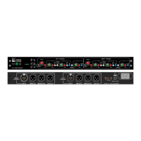
MSL-4 AND PSW-2 WITH CQ DOWN-FILL
3
This example shows the LD-2 used to integrate a system of
self-powered loudspeakers for a larger venue.
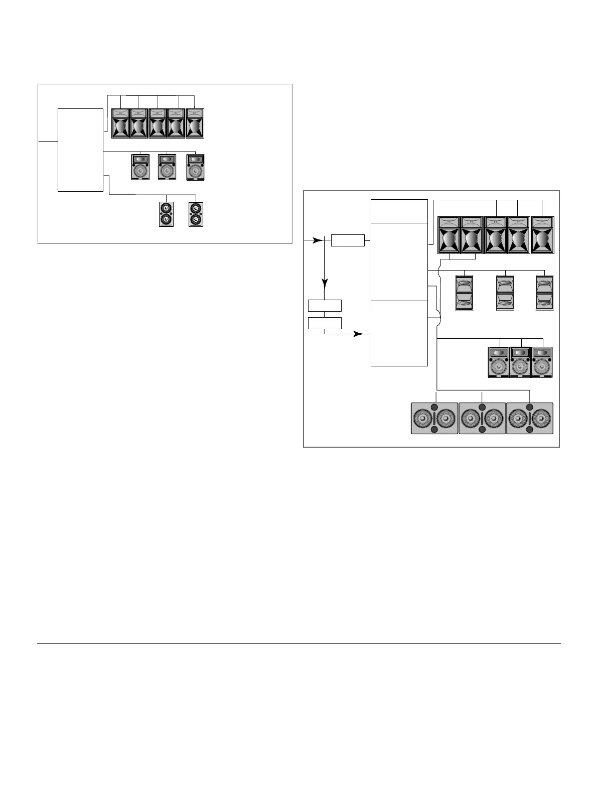
MSL-4 FLOWN FOR MAINS, CQ DOWN FILL, AND 650-P
Figure 9 shows half of the system using the Left channel;
identical connections can be used for the Right channel to
create the other half. The MSL-4 and CQ arrays are flown; the
650-Ps are on the floor.
The Mid-Hi output drives the MSL-4 flown array. Array EQ
switches should be in, to minimize the additional low-mid
energy from the combined CQ's and MSL-4's. The Lo Cut filter
should be switched out, as there is no significant overlap
between the MSL-4s and the 650-P with this physical
arrangement. The Left channel's Mid-Bass/Aux output controls
the CQ down-fill system. Because the primary section of this
array will have greater acoustic output than that of the down-
fill system, there will be audible and measurable low
frequency energy from the primary loudspeakers into the
downfill coverage area. To insure that these loudspeakers
combine properly in this intersecting downfill coverage area:
· Invert the polarity to the CQ's in order to align them to the
high frequency output of the MSL-4's and to reduce com-
bining in the low frequency range.
· Use the Mid-Bass/Aux Lo Cut filter to eliminate the LF rise
caused by the overlap in frequency response with the 650-P
· Delay the down-fill to compensate for the propagation
delay between the down-fill and primary loudspeakers in
the intersecting coverage area.
· The Mid-Bass and Sub crossover switch should be out.
The correct polarity for the 650-P subwoofers is dependent on
the height and distance of the measurement position relative
to the subwoofers and the flown loudspeakers.
We recommend that the entire system be measured, phase-
aligned, and equalized using the SIM System II Sound
Analyzer and CP-10 Parametric Equalizer.
Set the MSL-4 and 650-P to the same polarity; reverse the
polarity of the CQ. The polarity of the 650-P depends on the
distance of the measurement position from the subwoofer and
flown systems.
DIFFERENTIAL INPUTS
1. 0 dBV = 1 Vrms; 0 dBu = 0.775 Vrms; 0 dBm = 1 mWrms
2. Ratio of maximum sinewave to A-weighted noise floor.
3. Level set to unity gain (0 dB).
4. 0 dBV, 1 kHz sinewave input. Gain at +12 dB main channel,
+6 dB auxiliary channel.
Figure 8 The LD-2 with an MSL-4, PSW-2, and CQ downfill
Figure 9 The LD-2 with an MSL-4, Mid-Bass loudspeakers
(the DS-4P is shown), CQ, and 650-P
3. This arrangement will work with any suitable loudspeaker system,
e.g. DF-4, UPA-1P/2P, etc.