CHAPTER 4: QUICKFLY RIGGING
27
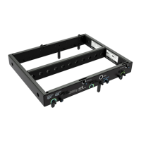
LEOPARD GUIDEALINKS
LEOPARD is equipped with four captive GuideALinks and
four mating links slots that link to adjacent LEOPARDs or
900-LFCs in flown and groundstacked arrays. Located at the
top corners of the cabinet, GuideALinks extend up and into
the link slots of the cabinet above it (Figure 16 and Figure 17),
or into the link slots of the MG-LEOPARD/900 grid or
MTF-LYON/LEOPARD transition frame. GuideALinks extend
and retract with knobs and are secured with two quick-
release pins: one each in the top and bottom cabinets. Each
LEOPARD loudspeaker ships with eight 5/16 x 0.063-inch
quick-release pins (black button) (PN 134.024).
CAUTION: GuideALinks must be secured with
the included quick-release pins. At no time
should the weight of the loudspeaker rest on the
GuideALink knobs when the links are fully extended
(without the pins inserted). GuideALink knobs are for
extending and retracting the links only.
LEOPARD Splay Angles
Front GuideALinks attach at splay angles of 0 or +5 degrees.
However, the front GuideALinks should almost always be
attached at 0 degrees, to ensure that coverage between
linked cabinets is continuous. When attached at 0 degrees,
the front GuideALinks act as a pivot point between the linked
LEOPARDs, with the splay angle between the units
determined by the rear GuideALink positions. When attached
at +5 degrees, the front GuideALinks add 5 degrees to the
splay angle configured with the rear GuideALinks, making it
possible to achieve splay angles of 11 to 15 degrees. To stow
the front GuideALinks, move them all the way down to STOW
and pin them.
TIP: Wide splay angles of 11 to 15 degrees
should only be used for downfill coverage, or for
steering coverage away from structures like balconies.
Rear GuideALinks attach at splay angles of 0.5 to 10 degrees.
The labels next to the rear GuideALinks indicate the splay
angle between cabinets and provide a guide for which of the
three pinning positions to use to secure the links (Figure 18).
As the links are moved down, the splay angle increases. To
stow the rear GuideALinks, move them all the way down to
STOW and pin them to the center pin position.
NOTE: The splay angles listed on the
GuideALink labels are for relative angles
between the center axes of the linked units. For
example, setting the GuideALinks to 5 degrees yields
a 5-degree downtilt of the lower unit to the upper unit.
How the loudspeakers relate to the floor, stage, and
seating angles in the venue depends on the orientation
of the grid, the angles of the loudspeakers in the array
above them, and other factors. MAPP prediction
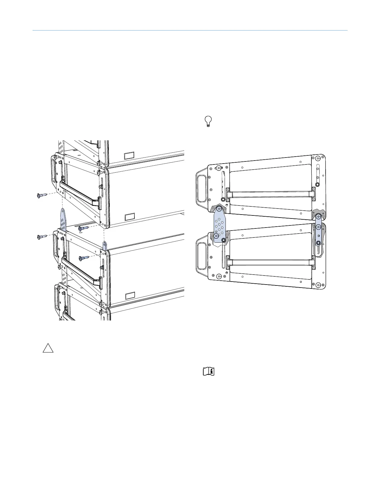
Figure 16: LEOPARD GuideALinks with Quick-Release Pins, Exploded
View
Figure 17: LEOPARD GuideALinks (Exposed) Attached at 0.5 Degrees