MG-3D/M MULTIPURPOSE GRID AND ACCESSORIES
PN: 05.132.036.01 B2
Page 22 of 32
Meyer Sound Laboratories Inc.
www.meyersound.com
T: +1 510 486.1166
F: +1 510 486.8356
M3D/M3D-SUB GROUND-SUPPORTED CONFIGURATIONS
By simply flipping the MG-3D/M multipurpose grid over from its flown configuration, it can be used to provide ground
support for an M3D/M3D-Sub array. The MG-3D/M grid provides two positions — front and rear. Either position may
be used to stack M3D loudspeakers, although the front position is most useful for stacking a predominantly up tilted
M3D array. In a ground-supported configuration, the MTL-3D transition link becomes the rear link between the MG-
3D/M grid and the first M3D/M3D-Sub cabinet. The captive front CamLink is used between the first M3D/M3D-Sub
cabinet and the MG-3D/M grid, providing up to a full 5° of up tilt.
CAUTION: For safety reasons, ground-supported arrays of more than six M3D/M3D-Sub loudspeakers
using the MG-3D/M grid should be avoided. Larger stacks can become unstable.
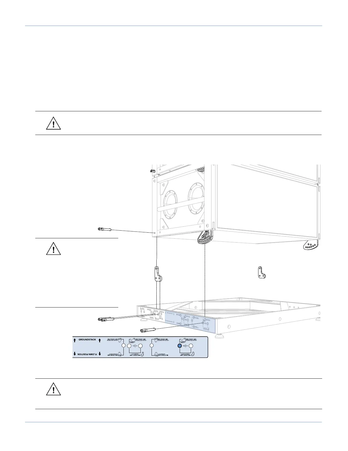
Install the MTL-3D transition links and M3D/M3D-Sub captive rear links as shown into the MG-3D/M grid, using the
1/2" x 2.5" quick release pins (QRPs).
CAUTION: When ground supporting an M3D/M3D-Sub array on an MG-3D/M grid, always keep the
center of gravity within the footprint of the leveling feet. To further secure larger arrays — particularly in
outdoor situations — use a tie down or extra ballast weight on the grid.
CAUTION: Always
use two 1/2" M3D
QRPs to secure the MTL-
3D transition links and
one to secure the captive
rear links to the MG-3D/M
grid, and be sure to lock
them into place. Do not
use the MILO 3/8" QRPs.

 Loading...