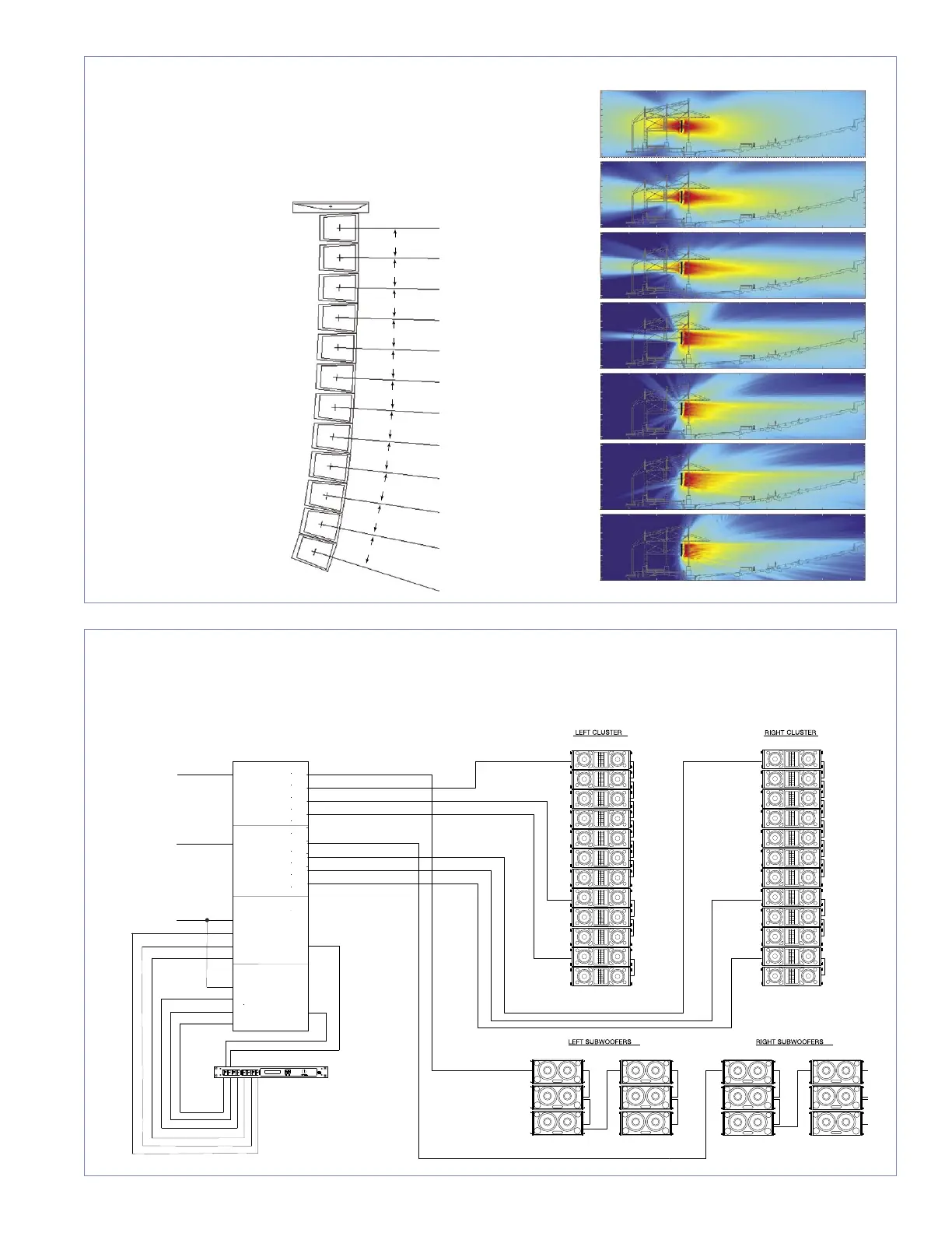
Signal Flow for a Typical Reinforcement System
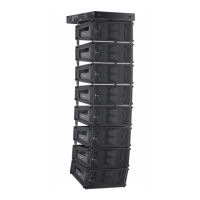
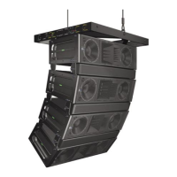
MICA Vertical Splay and Coverage
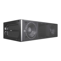
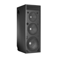
MICA loudspeakers permit versatile arrays and are compatible with other Meyer Sound reinforcement loudspeakers, giving sound designers
maximum freedom to customize systems for their needs. This block diagram illustrates the signal flow for a typical sound reinforcement
system using 12 MICA cabinets per side for the main arrays.
These illustrations show how the splay between adjacent cabinets in a MICA
array may be adjusted to tailor coverage for a specific venue. The MAPP
Online plots on the right illustrate the vertical directivity characteristics of the
array on the left, with a section view of an example venue superimposed.
2 kHz
4 kHz
1 kHz
500 Hz
250 Hz
8 kHz
125 Hz
Digital Delay
2 In x 6 Out
Digital Delay/EQ
LD-3
Channel A
IN SUB OUT
CH 1 OUT
CH 2 OUT
CH 3 OUT
Channel B
IN SUB OUT
CH 1 OUT
CH 2 OUT
CH 3 OUT
Channel A
INSERTS SENDS
IN SUB OUT
Full Range
IN CH 1 OUT
Post Array
IN CH 2 OUT
Post Array
IN CH 3
Post HPF
Channel B
INSERTS SENDS
IN SUB OUT
Full Range
IN CH 1 OUT
Post Array
IN CH 2 OUT
Post Array
IN CH 3
Post HPF
Main
Left
Main
Right
Optional
Subwoofer
Mono
(6) 700-HP (6) 700-HP
(12) MICA (12) MICA

 Loading...