ULTRA XP OPERATING INSTRUCTIONS
33
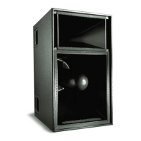
2. Insert the five exposed conductors into the five cable holes in a Phoenix 5-pin female cable mount connector. Use the
following wiring scheme.
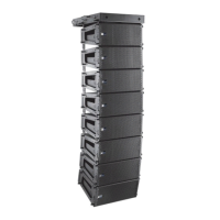
3. Secure the conductors by tightening the five screws in the Phoenix cable mount connector. Screws should be torqued to
5–6 Nm(4.4–5.3 In-Lbs).
CAUTION: Screws should not be inserted into the Phoenix connector while the connector rests in a mating
plug. Doing so will damage the contacts. During assembly, the Phoenix connector should only be held in place
externally.
4. If the other (ECO-M) end of the cable has not been stripped, strip the outer shielding 1 inch and then strip the black, red,
blue, and white wires 0.275 inch.
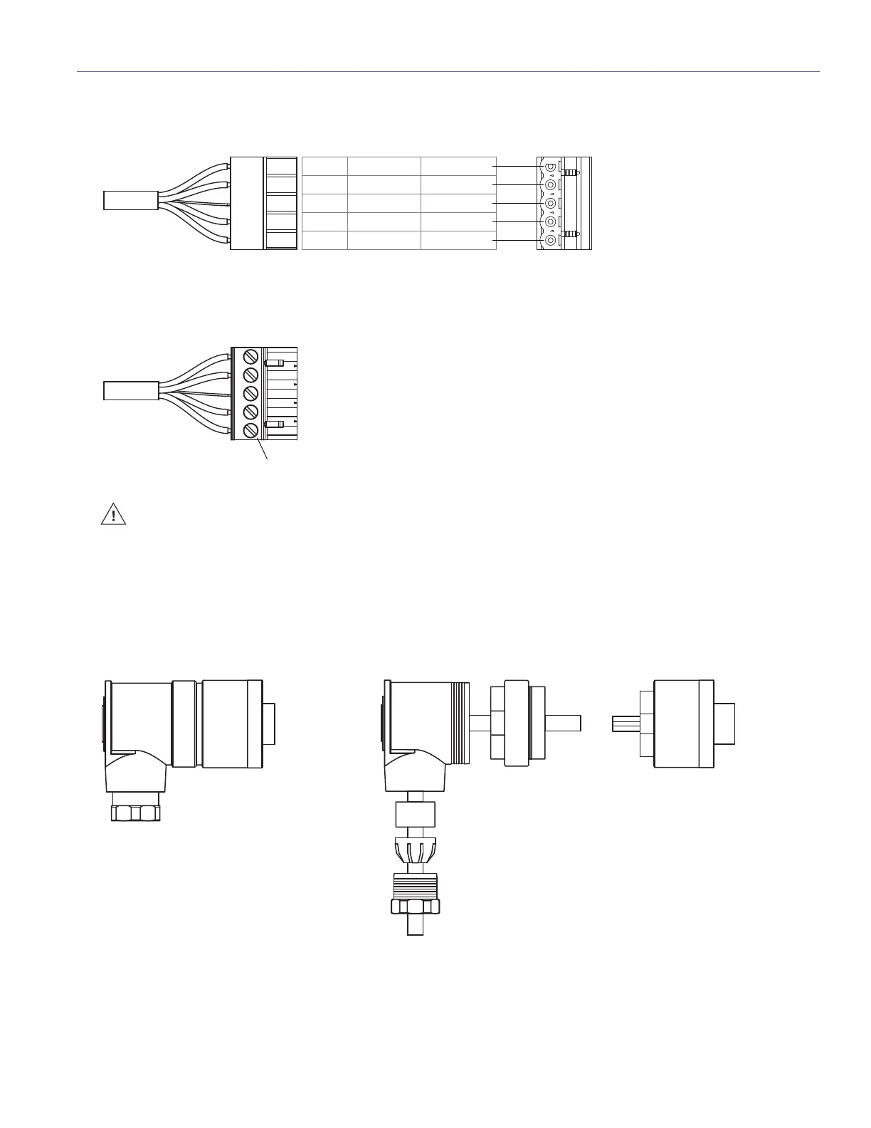
5. Disassemble the ECO-M 7-pin female connector and feed the stripped cable through the pressing screw, pinch ring,
seal, angled hood, and sleeve.
Pin Destinations for Phoenix 5-Pin Female Cable Mount Connector
ECO-M 7-Pin Female Cable Mount Connector, Assembled (Left) and Disassembled (Right)
Pin 1 Black 48 V DC (–)
Pin 2 Red 48 V DC (+)
Pin 3 Shield drain Audio shield
Pin 4 Blue Audio (–)
Pin 5 White Audio (+)
Pressing screw
Angled hood
Pinch ring
Seal
Sleeve Insert connector

 Loading...