APPENDIX B: ASSEMBLING LOUDSPEAKER CABLES
34
6. Solder the five exposed conductors to the (1, 2, S, 5, and 6) pins on the ECO-M insert connector using the following wir-
ing scheme.
7. Reassemble the ECO-M 7-pin female connector:
■ Return the seal and pinch ring to the angled hood and secure it with the pressing screw.
■ Return the sleeve to the angled hood and secure it with the insert connector.
8. Verify the wiring polarity is correct for both cable ends.
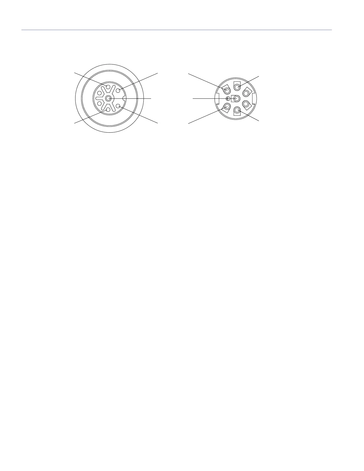
Pin Destinations for ECO-M 7-Pin Female Cable Mount Connector
Pin 6, White,
audio (+)
Pin 5, Blue,
audio (–)
Pin S, Shield drain,
audio shield
Pin 1, Black,
48 V DC (–)
REAR
FRONT
Pin 2, Red,
48 V DC (+)
Pin 5, Blue,
audio (–)
Pin 2, Red,
48 V DC (+)
 Loading...