18
CHAPTER 5
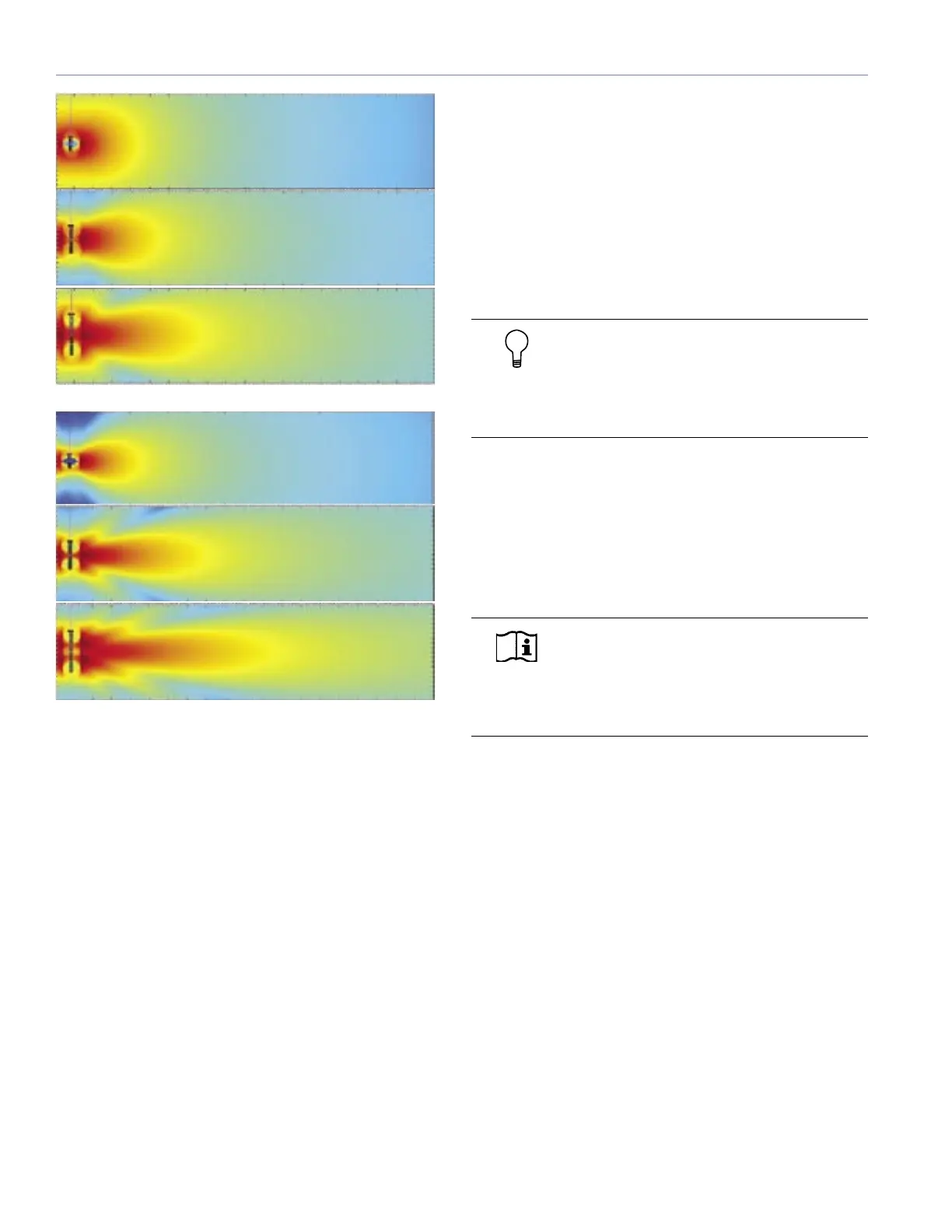
Figure 5.1. MAPP Online Pro predictions of 6-, 12-, and 18-cabinet M’elodie
line arrays at 125 Hz (top) and 250 Hz shows how directionality increases
with length of array.
Designing a Line Array System
Designing and deploying a line array system will typically
have the following objectives:
■ Even horizontal and vertical coverage
■ Uniform SPL
■ Uniform frequency response
■ Sufficient SPL and headroom for the application
To achieve these objectives, fine-tuning a design for a
M’elodie array is dependent on three factors:
■ Number of Array Elements. Determining the number
of elements to use is critical. The number of elements
drastically affects the SPL and headroom available from
the system as well as the uniformity of coverage in both
SPL and frequency response. The number of elements
profoundly effects the directivity at lower frequencies.
■ Vertical Splay Angles. Changing the splay angles
between cabinets has a significant impact on vertical
coverage for the high frequencies, with the result that
narrower vertical splay angles produce a higher Q
vertical beamwidth, while wider splay lowers the Q at
high frequencies. In general, the splay angles do not
affect the vertical coverage at lower frequencies.
■ Horizontal Coverage. Horizontal coverage for a single
M’elodie array can be considered constant regardless
of the number of array elements or the angles between
them.
TIP: When more than one array is used, the
angle between line arrays in the horizontal
plane can be changed to meet additional design
requirements (for example, more horizontal
coverage, avoid wall reflections, etc.).
With two different technologies (low-frequency cone
radiators and high-frequency horn) built into each M’elodie
cabinet, achieving these goals becomes a multi-step
process, with different strategies:
■ Lower and higher frequencies
■ Long throws and short throws
NOTE: MAPP Online Pro, covered Chapter
6 of this manual, is the tool of choice to
enable you to make accurate and comprehensive
predictions for optimal coverage(s) during the
design phase.
High-Frequency Design Strategies
Planning for high-frequency coverage is a matter of
deciding the number of elements and fine-tuning the splay
angles between cabinets. The number of elements does
not necessarily have a significant impact on SPL at high
frequencies (it will at low frequencies), but can profoundly
affect vertical coverage and throw capabilities of the array.
For the far field, a smaller mechanical splay angle between
cabinets achieves superior throw through better coupling
to compensate for energy lost over distance. The longer
the throw needed, the more elements needed with smaller
angles at the top of the array.
In the near- to mid-field, larger splay angles are used to
increase vertical coverage.
250 Hz
6 M’elodie
Cabinets
125 Hz
12 M’elodie
Cabinets
18 M’elodie
Cabinets
6 M’elodie
Cabinets
12 M’elodie
Cabinets
18 M’elodie
Cabinets

 Loading...