5
CHAPTER 1
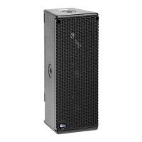
Self-powered and compact, UPM-1P and UPM-2P
loudspeakers combine advanced technology with equally
advanced power capabilities. Understanding power
distribution, voltage and current requirements, as well as
electrical safety issues, is critical to the safe operation of
the loudspeakers.
AC POWER
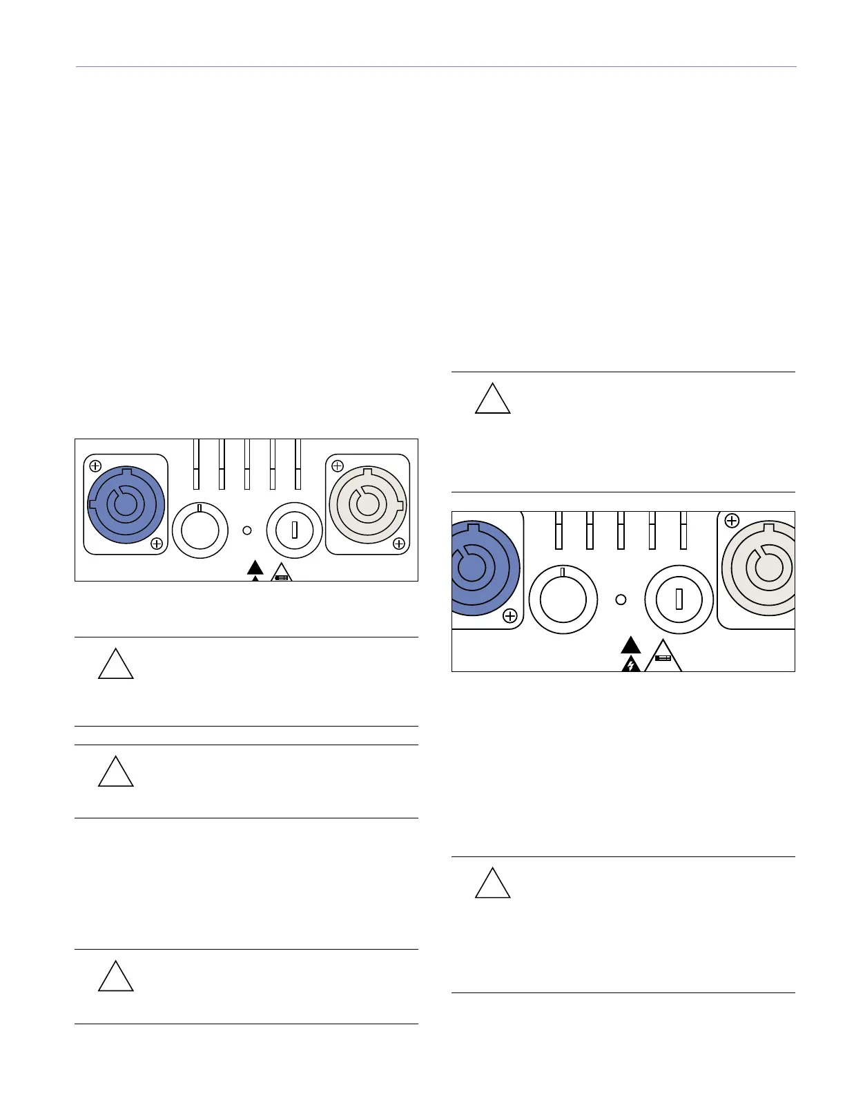
UPM-1P and UPM-2P loudspeakers use a PowerCon
®
three-pole AC mains system with locking connectors
to prevent accidental disconnection. They may also be
daisy-chained by using the grey connector (Figure 1.1)
to loop units together. The blue connector serves as the
power input; to loop additional units, simply attach a cable
from the grey connector of the first loudspeaker system to
the blue connector of the second, and so on. One cable-
mount loop-out grey connector is shipped with the unit.
2
3
0
115
!
AC Input 115 / 230V~
50-60Hz 3A MAX
AC Loop Output 115 / 230V~
50-60Hz 15A MAX
Class 1 Wiring
SET VOLTAGE BEFORE APPLYING POWER
RISK OF FIRE REPLACE WITH F3.15A - 250V FUSE
Meyer Sound
Model UPM-1P
CAUTIONS:
F3.15A 250V
ATTENTION:
UTILISER UN FUSIBLE DE RECHANGE DE M ME TYPE DE F3.15A - 250V
Figure 1.1. You can daisy-chain UPM-1P and UPM-2P loudspeakers
using the grey connector.
CAUTION: Do not loop more than four
UPM-1P or UPM-2P loudspeakers from the
loop out connector when driven at 115 volts and
not more than eight when driven at 230 volts.
CAUTION: Ensure that you select the
correct power plug for the AC power in the
area in which you use your loudspeaker.
The power supply suppresses high voltage transients up
to several kilovolts and also filters EMI (radio frequencies
and noise present) on the incoming AC voltage. The UPM-
1P can withstand continuous voltages up to 264 volts and
allow any combination of voltage to GND (that is neutral-
line-ground or line-line-ground).
CAUTION: Continuous voltages higher than
265 volts may damage your UPM-1P or
UPM-2P loudspeaker.
Voltage Selection
Two versions of both the UPM-1P and UPM-2P
loudspeakers are available: a switchable 115/230-volt and
a non-switchable 100-volt version. The non-switchable
100-volt version will operate properly when receiving
between 87 and 113 volts; the switchable version requires
you to check the voltage switch and set it to either 115 or
230 volts. When set to 115 volts, the UPM-1P and UPM-2P
will operate properly when the AC remains within the range
of 105 to 130 volts. If set to 230 volts, the unit operates
safely and without audio discontinuity within the range of
210 to 264 volts. Operating outside these ranges or with
the voltage switch set improperly could damage the unit.
CAUTION: To avoid damage to the unit,
check the AC voltage selector switch
(Figure 1.2) on the user panel before plugging in
the unit and applying power. Set the switch to
local AC voltage. Always unplug the power cord
before changing the voltage selector switch.
2
3
0
115
!
AC Input 115 / 230V~
50-60Hz 3A MAX
AC Loop Output 115 / 230V~
50-60Hz 15A MAX
Class 1 Wiring
SET VOLTAGE BEFORE APPLYING POWER
RISK OF FIRE REPLACE WITH F3.15A - 250V FUSE
Meyer Sound
Model UPM-1P
CAUTIONS:
F3.15A 250V
ATTENTION:
UTILISER UN FUSIBLE DE RECHANGE DE M ME TYPE DE F3.15A - 250V
Figure 1.2. Rear panel AC inlet and voltage selector switch
After applying AC power, the system is muted while the
circuitry charges up and stabilizes. After two seconds, the
following occurs:
1. The main power supply slowly ramps on.
2. The green On/Temp LED on the user panel lights up,
indicating that the system is enabled and ready to
pass audio signals.
CAUTION: If the On/Temp LED does not
illuminate or the system does not respond
to audio input after 10 seconds, remove AC power
immediately. Verify that the voltage is within the
proper range. If the problem persists, please
contact Meyer Sound or an authorized service
center.
CHAPTER 1: POWER REQUIREMENTS
Blue
Grey
Voltage selector
Fuse cap

 Loading...