(7)
For snow plow light installation see separate instructions.
Orange wire on Harness (49) will attach to both orange wires of the “B”
harness supplied in the Light Module Kit. Reference Form 1-757
Route Cables “C” (Yellow) from module to Harness (49). Connect both “C”
Harness female ends to the male corresponding ends of the Harness (49).
Connect both male ends from the snow plow light to the female ends on
the Plow Side Harness (29).
Check snow plow light blinkers to make sure the wires have not been
reversed.
Note: All electrical connections should have both ends coated with a dielectric
grease, Meyer Part No. 15632, prior to nal installation. This will ensure a good
connection and help in preventing corrosion.
K. Refer to Operation and Maintenance Manual for complete controller
operation.
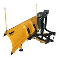
L. After all electrical connections have been made the drop speed of the plow
may be evaluated / adjusted. To adjust, loosen the hex nut and adjust in
to slow the drop speed and out to make it faster. After ideal drop speed it
achieved, retighten the hex nut. See below.
After cycling of the plow, recheck oil level.
E-58H Lower Adjustment (left side of vehicle):
Loosen jam nut and turn screw clockwise to slow the drop of the plow and counter
clockwise to speed the drop of the plow. Tighten jam nut
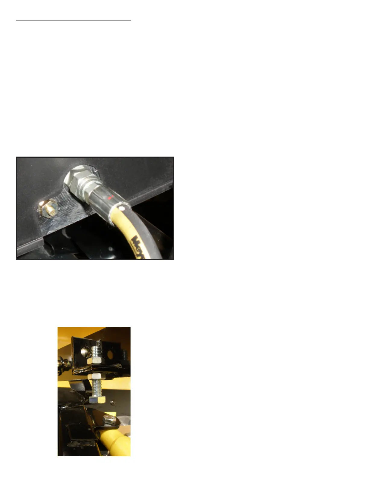
M. Assemble adjustable stacking stop bolts to lift frame (11) using 5/8-11 x
2-3/4” bolts (18), lockwashers (21) and jamnuts (55). See below.
Note: Adjustment must be made after moldboard assembly is installed.
Adjustment bolts (61) should make contact with the a-frame before any
part of the A-Frame/ Sector or moldboard come in contact with the lift
arm and, or hydraulic unit while raising the snowplow or stacking snow.
Moldboard should be checked in all positions.
 Loading...