MFJ-1798 Vertical Antenna Instructions
11
9- Find the end of the 1-3/8" tubing that has a 1/4" hole
located around four inches from the end. Insert the solid
fiberglass base insulator on the base mount into this end
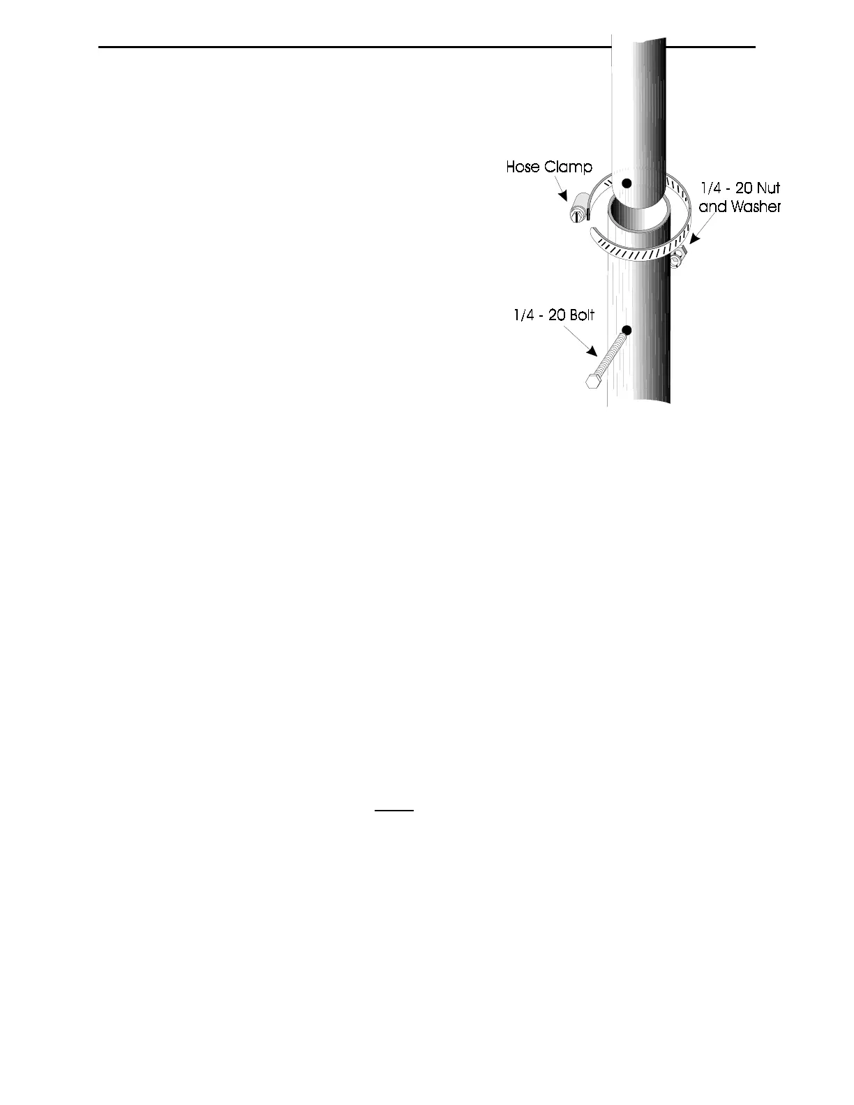
of the tubing. Use a 1/4" bolt to secure the tubing. Place a
hose clamp over the outer end of the slit area of the
tubing.
10- Find the end of the 1-1/4' diameter tubing that has a
1/4" hole one inch from the end. Slide this end into the 1-
3/8" tubing used in step 9. Secure the tubing with a bolt
and a hose clamp over the outer end of the slit.
11- Find the end of the 1-1/8" diameter tubing with a hole
at 1" from end. Slide this end into the tubing used in step
10. Secure it with a bolt and a hose clamp over the end of
the slit.
In the following steps you will refer to figure 3. Locate
the following parts:
Two 10-32 x 3/8" nuts (B2)
Two 10-32 x 1-3/4" screws (B3)
Eight 6-32 x 5/8" screws (B3)
Two #10 split washers (B4)
Eight 6-32 x 3/8" nuts (B4)
One red plastic cap (B5)
One rectangular support bracket (C1)
Three triangular support brackets (C1)
One set of fiberglass and aluminum counterpoise support assembly plates (C2)
12- Position the counterpoise mounting plate so that the edge lip (aluminum side) is facing up.
Assemble the counterpoise mounting plate by using eight 6-32 x 5/8" screws to secure the three
triangular and one rectangular support brackets as shown in the drawing. All the edge flanges
should point clockwise. Be certain that the rectangular plate's edge flanges are facing (and next
to) the 2 meter element's mounting hole.
Note:
Do not tighten these screws at this time.
13- Position the plate so that the brackets are facing the base of the antenna. Slide the plate over
the 1-1/8" tubing (top of antenna). Align the holes and secure the plate with two 10-32 x 1-3/4"
screws with split washers under the nuts. Tighten the eight 6-32 support bracket screws installed
in step 12 and place the plastic cap plug over the top of the tubing.