MFJ-1798 Vertical Antenna Instructions
13
NOTE: Make sure all brackets are
assembled the in the same manner
(fit on top of each other the same
way). This is to help you to mount
them on the same side of the
antenna and keep them lined up.
NOTE:
At this point it will be useful to "prop up" the element
with a small support.
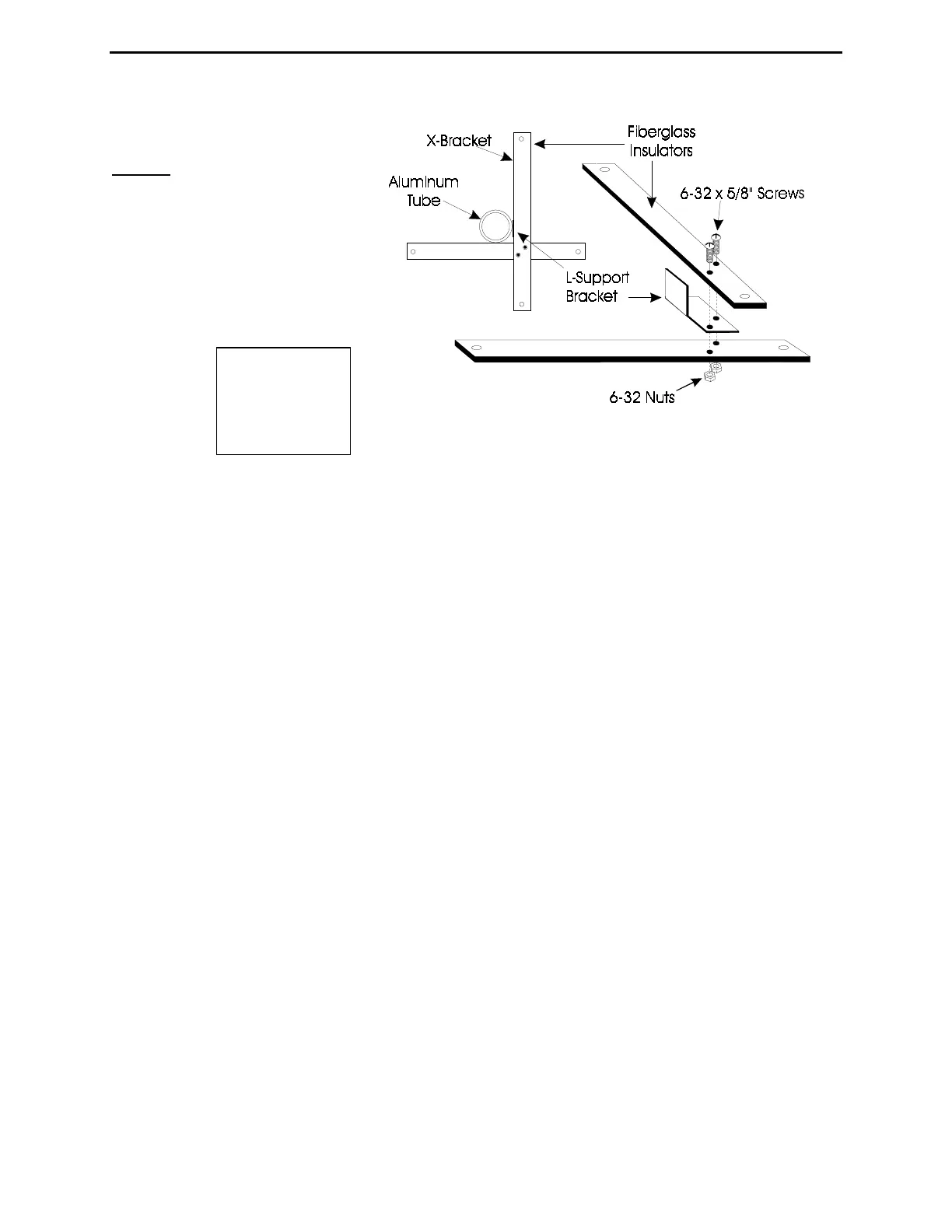
16- Place a hose clamp over the 1-1/8" tubing near the junction of the 1-1/4" tubing. Install the
"X" bracket under this clamp. Align the holes in the "X" bracket with the holes in the
counterpoise support plate. Secure the bracket with the hose clamp.
17- Using a similar procedure, install the second "X" bracket approximately four feet closer to
the base mount than the position of the first bracket.
18- Install the remaining fiberglass "I" bracket and hose clamp approximately eight feet lower
than the first "X" bracket. Position it parallel with any two adjacent holes in the square support
section of the feed plate and the "X" brackets. After aligning it can be secured with the clamp.
Locate the following parts:
Six 3/16" ID couplers (B5)
Four 55" threaded rods (A)
Two 72" non-threaded rods (A)
One 66.5" non-threaded rod (A)
One 48" non-threaded rod (A)
One 41" non-threaded rod (A)
One 15" non-threaded rod (A)
Twelve 6-32 x 1/4" screws (B12)
Eight 10-32 nuts
19- Install all twelve 6-32 screws finger tight in the couplers.
20- Slide four couplers half-way over the non-threaded end of the four 55"
threaded
rods. Slide
two couplers half-way over the ends of the two 72" rods. Secure the couplers.
Figure
4