MFJ-1798 Vertical Antenna Instructions
16
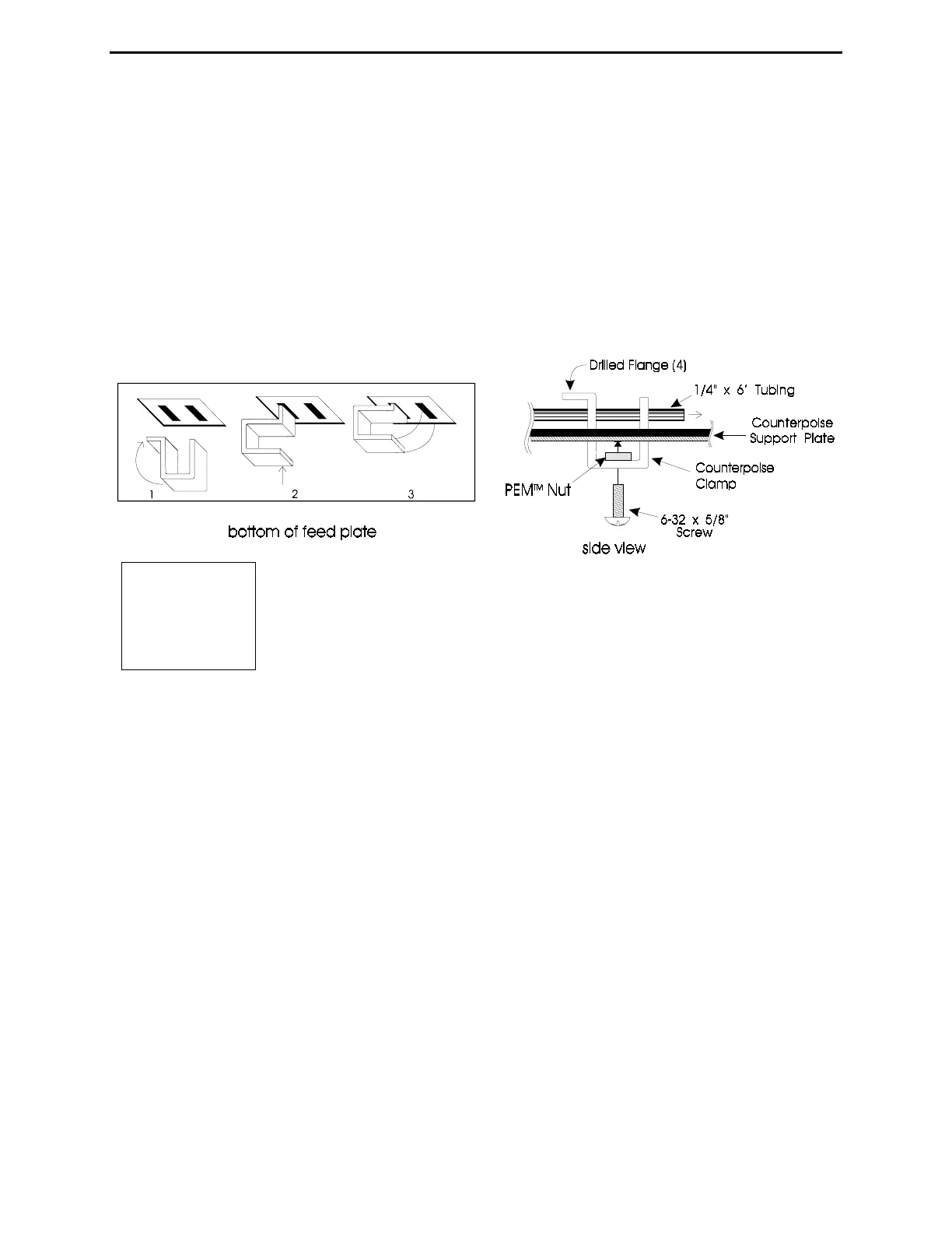
screws into the
PEM
TM
nuts, from the outside end, of three drilled flange counterpoise clamps
(Figure 6).
30- Install the four other screws by passing them through the
solder lungs of the counterpoise clamp wires, then threading them
into the counterpoise clamps with no flange (Figure 6).
31- Thread a 6-32 nut down to the head of a 6-32 x 5/8" screw. Pass the screw through the solder
lug on the red lead that connects to the capacitor junction of the Matching Network. Thread the
screw into the remaining drilled flange counterpoise clamp (see Figure 5).
32- Install the counterpoise clamp with the red wire attached in the
innermost slot located next to the square support bracket and the 2 meter
element. Make sure the drilled flange is pointing outward (see Figures 6 and 7).
33- Install a no flange counterpoise clamp in the outside slot in the fiberglass counterpoise
support plate in line with the clamp installed in the previous step.
34- Slide the empty end of the remaining 1/4" OD x 6' long aluminum element through the clamp
holes. Tighten the clamp screws to secure the tubing. Use a 5/16" nut driver or small wrench to
snug the nut down on the solder lug (see Figs. 6 and 7).
Note: Make sure the element end is between 1/4 and 1/2" away from the main element 1-
1/8" tubing. Be sure that the solder lugs are only touching the metal they are bolted
to, and NOT accidentally touching (or very close to) any other metal parts!
35- Connect the white wire (from trace that connects to the coax shield) by placing the lug over
either 6-32 mounting screw on the rectangular counterpoise plate support bracket. Installing a
new 6-32 nut over the solder lug to secure it (see figure 7).
Figure
6