MFJ-1798 Vertical Antenna Instructions
20
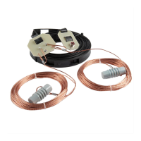
Locate the following parts:
Two 3/16" x 6' solid rods (A)
One 20 meter adjustable element clamp (C3)
One 6-32x 5/8" screw (B3)
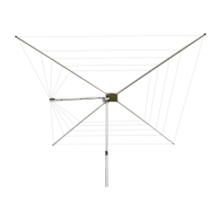
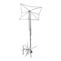
46- Install the 20 meter adjustment rods (two 3/16" x 6' solid rods) using the 20 meter clamp that
fits in the loading coil angle mount bracket. About 5' of rod should extend from each side.
Tighten the 6-32 x 5/8" screw to lock the rods in place (see Figure 10 on the following page).
47- The antenna assembly is now complete, it can be tested using a transceiver on low power or
with an SWR analyzer such as MFJ-249 or MFJ-259. It should be tuned before mounting it in
any elevated location.
WARNING! You can be killed if the antenna, feed line, or the
equipment used to install the antenna accidentally contacts any
utility lines. Never install an antenna near power lines!
1.
Be careful while climbing and carrying the antenna. It is heavy enough to cause you to
loose your balance if it is handled too casually or if the counterpoise or the capacitance
spokes are snagged on a gutter, ladder, tree limb, or any other object.
2.
Mount the antenna high enough so that it is out of reach. The ends of the capacitance
spokes, and other areas of the antenna, can cause eye injury, serious RF burns or both.
3.
Make sure that the mast is sturdy enough to support 20 pounds of weight and a wind
load of approximately 3 square feet.
Figure
9