MFJ-1798 Vertical Antenna Instructions
19
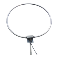
Four short capacitance hat spokes (A)
Sixteen 6-32 x 1/4" screws (B2)
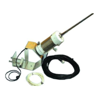
One 30" fiberglass loading coil assembly (A)
Four hose clamps (D)
Warning:
Only tighten the screw that fastens the loading coil
terminal lugs to the capacitance hat if the ring is
loose. Never excessively tighten the screw or you can
BREAK the fiberglass form. If the terminal lugs are
loose, tighten the NUT against the lug
.
43- Install the short 6-32 x 1/4" screws in the rings of loading coil assembly. Do not thread the
screws completely in. Install six long capacitance spokes in the six holes in the 80-meter
capacitance hat ring. Tighten the screws until the spokes are snug. At this point you should be
able to stand the coil form on its end. Use either a #5 or #2 screwdriver here (see Figure 9).
44- Install the six remaining long spokes in the six holes in the 40 meter capacitance hat ring,
then install four short spokes in the 30 meter capacitance hat ring.
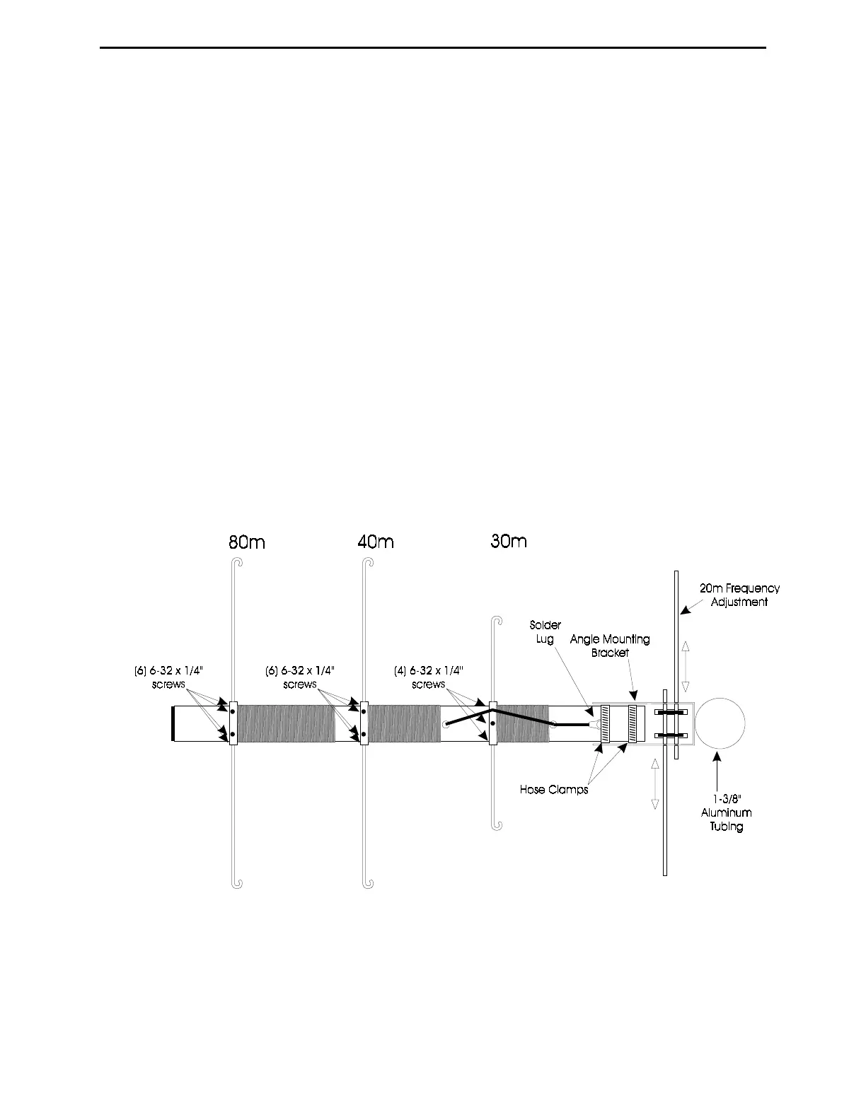
45- Mount the coil assembly in the angle mounting bracket. Place the solder lug under the first
hose clamp. Tighten both hose clamps.
Do not over tighten the hose clamps, you may break
the fiberglass form, or the clamps.
See Figure 10.