MFJ-1798 Vertical Antenna Instructions
18
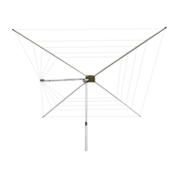
38- Mount the three remaining 1/4" x 6' long tubes in
position using the remaining clamps. Be sure that the
clamps with the drilled flange are in the innermost slots and
have their flanged ends pointed outwards. Be sure the tubes
are between 1/4 and 1/2 inch from the 1-1/8" main element.
Tighten the no-flange counterpoise clamps ONLY.
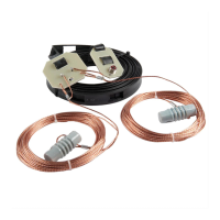
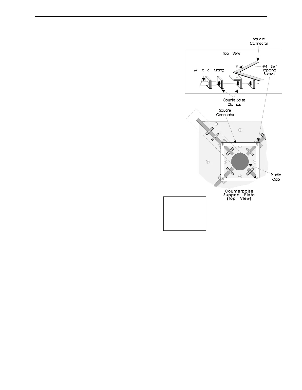
39- The counterpoise wires connected together with the
square hollow center plate. Use four #4 self- tapping screws
to attach the hollow center square plate to the flange holes
of the inner counterpoise clamps (see Figure 8). DO NOT
OVER TIGHTEN THE SCREWS but be sure that they are
fully seated on the plate's surface.
40- Use a 5/16" nut driver to tighten all 6/32 nuts on the
flanged counterpoise clamps and the non-flanged clamps.
Make sure that counterpoise rods are mechanically
secure.
WARNING:
The counterpoise tubing must stay at least
1/4" from the 1-1/8" tubing.
41- Connect the outer ends of the counterpoise together using the wire
provided. Connection is made by wrapping the wire once around the 4-40
screw between the flat washer and the cap nut on the end of the
counterpoise rod before tightening the screw.
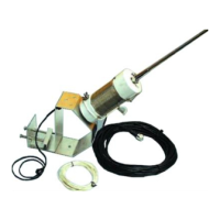
41- Mount the angle mounting bracket of the trap assembly at the bottom of the antenna and
make sure it is pointing to the opposite side of the 17m stub and away enough from the balun
(refer to Figure 10).
42- Raise the antenna to a temporary mast (5-8'), and secure it using the two U-bolts on the
mounting base.
Warning:
Be especially careful when moving or mounting this antenna. The weight
and length of this antenna can cause a loss of balance if handled by an
inexperienced person, or if the counterpoise or a capacitance spoke
accidentally becomes snagged on a gutter, a tree limb, or any other object.
Locate the following parts:
Twelve long capacitance hat spokes (A)
Figure
8