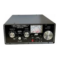
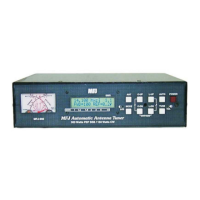
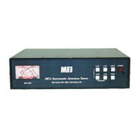
MFJ-941E Versa Tuner II
2
INSTALLATION:
1.
The tuner should be placed in a location where operation will be convenient. The ceramic
feed through insulators will have high RF voltages if random wire or balanced line
operation is used. These voltages can cause serious RF burns if touched when
transmitting.
NOTE
:
Locate the tuner so the rear is not accessible during operation.
2.
The MFJ-941E should be installed between the transmitter and antenna. A coaxial line
should be connected to the transmitter and the SO-239 coax TRANSMITTER connector
on the back of the tuner.
3.
One or two coax-fed antennas may be connected to the SO-239 coax connectors marked
COAX 1 or COAX 2. Coax 1 and Coax 2 antennas may be connected directly to the
transmitter, bypassing the tuner, by setting the ANTENNA SELECTOR switch to COAX 1
DIRECT or COAX 2 DIRECT, respectively.
4. A random wire antenna may be connected to the five-way binding post marked WIRE.
The random length wire should be long, high, and as clear of surrounding objects as
possible. For optimum operation, the wire antenna should be a quarter wave-length or
longer at the operating frequency. Do NOT ground the random wire antenna. The tuner
should be well-grounded to the transmitter. A binding post marked GROUND is provided
for ground connections.
5.
A balanced line-fed antenna may be connected to the two five-way binding posts marked
BALANCED LINE. A jumper wire from the WIRE binding post, as indicated by a dotted
line on the MFJ-941E, should be connected to one of the posts of the BALANCE LINE.
This couples the MFJ-941E to the balanced line through a 4:1 balun.
NOTE
:
Either a balanced line or a random wire antenna may be connected to the MFJ-941E at
one time. If a random length wire is used, care should be taken to assure that no
jumper wire is between the WIRE binding post and the BALANCED LINE.
6. An external 50 Ohm dummy load may be connected to the EXT. DUMMY LOAD
connector located at the rear of the tuner.