MFJ-941E Versa Tuner II
3
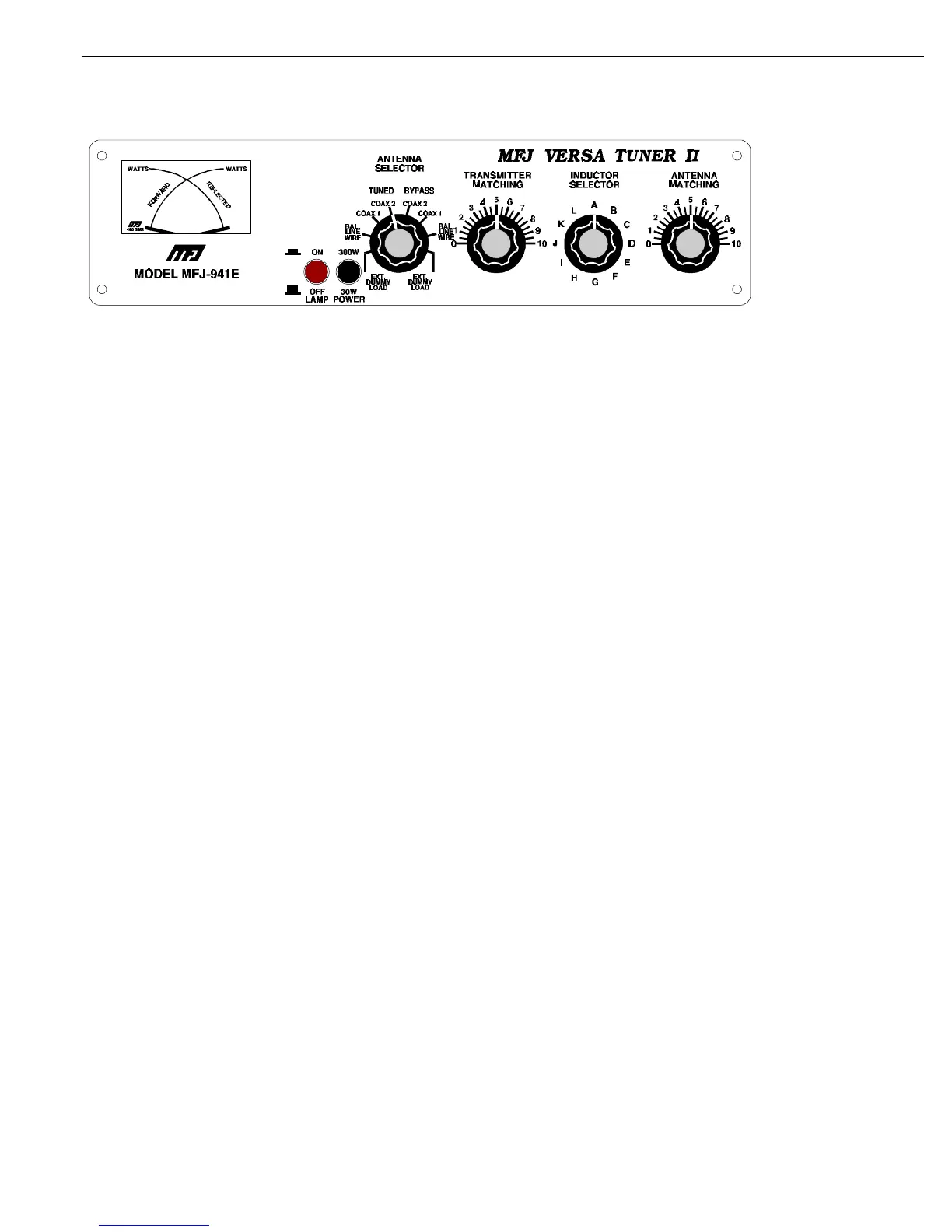
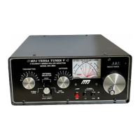
MFJ-941E Front Panel
USING THE MFJ-
941E:
The INDUCTOR switch on the MFJ-941E represents maximum inductance at position "A" and the minimum inductance
at position "L". Lower inductance is needed at higher frequencies than at low frequencies for the same impedance. The
TRANSMITTER and ANTENNA controls represent maximum capacitance at position 10. For optimum operation of the
MFJ-941E, the transmitter must be tuned to a 50 Ohm output impedance at the frequency of operation. The ANTENNA
SELECTOR switch should be set to DUMMY LOAD for tuning up the transmitter.
NOTE: The transmitter should always be tuned at a low output power.
After the transmitter is properly tuned, the ANTENNA SELECTOR should be set to the desired antenna and the tuner
adjusted for a minimum SWR as described below. DO NOT readjust the transmitter loading control setting after loading
it to 50 Ohms.
NOTE:
When using the MFJ-941E for receiving only, tune as described in Steps 1 and 2.
TUNER ADJUSTMENT:
1. Set the TRANSMITTER and ANTENNA controls to 5. In this position the capacitors are
half-open.
2. Rotate the INDUCTOR control until maximum noise is obtained with the transceiver in the
receiving mode.
CAUTION: Do not operate the ANTENNA selector switch while transmitting!.