MFJ-989D VersaTuner V Instruction Manual
10
Wire
Jumper Wire
Install
<
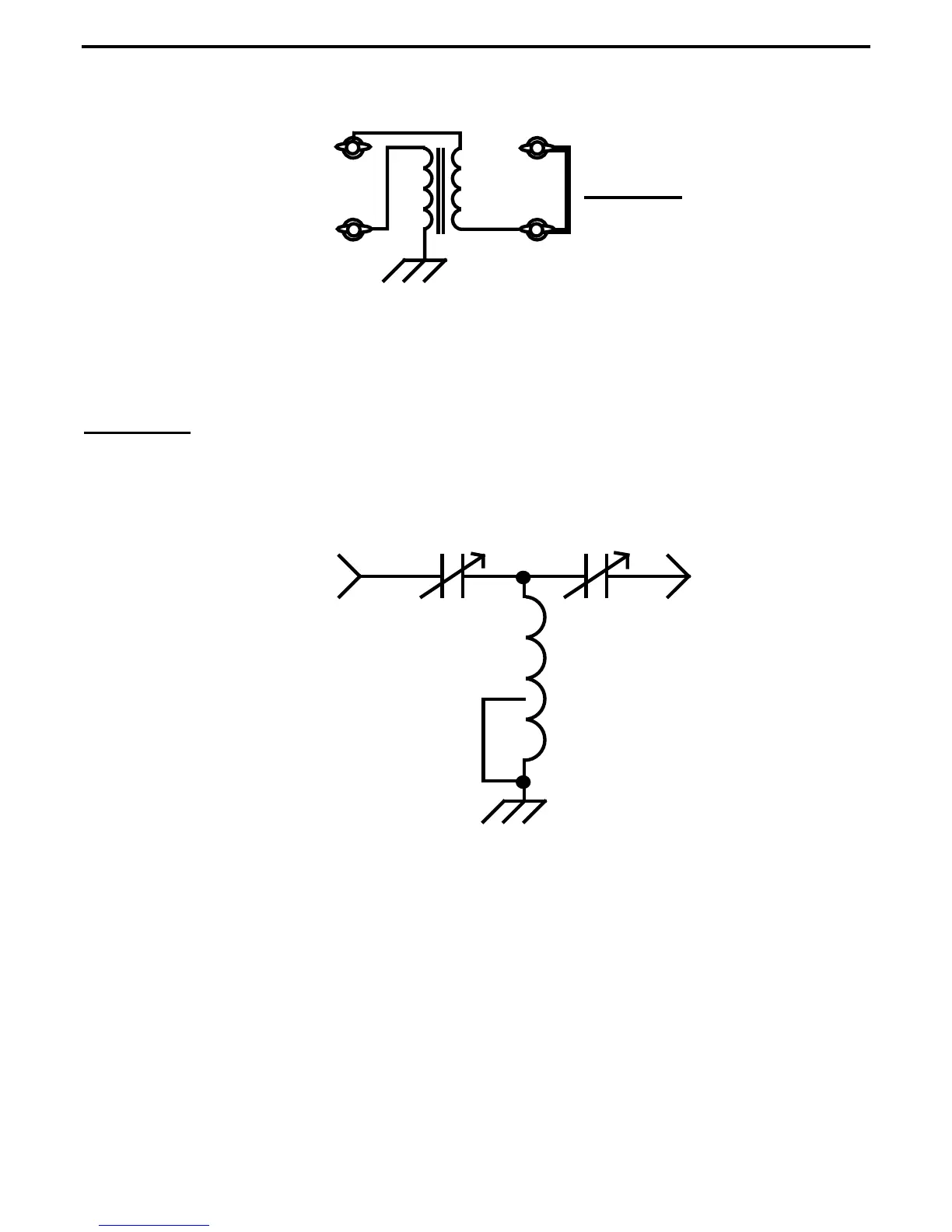
Bal. Line
Balun
To place the balun in line and energize the Bal. Line terminals, connect a Jumper from the unbalanced
Wire terminal post to the terminal post directly below it. The jumper-wire path is labeled on back panel
for reference. Note that the T-network is always in line when the Antenna Selector is switched to the
Wire/Bal. Line position.
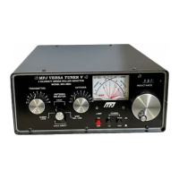
T-Network
1.) The Network Configuration: The T-network gets its name from the distinctive shape of the
components making it up (shown below):
>
Transmitter Antenna
Inductor
This network configuration is especially practical for amateur-radio tuners because it can match an
unusually wide range of loads into 50-Ohm equipment. The T-configuration using two series capacitors
and a shunt inductor belongs to the high-pass filter family and, as such, it does little to suppress
transmitter harmonics. However, modern transceivers and amplifiers must meet stringent harmonic
suppression requirements on their own to satisfy FCC requirements, so there's little need for high-
frequency suppression in the tuner.
2.) The C-high L-low Rule: With three tunable elements(C-L-C), the T-Network is able to provide a
low-SWR match into a 50-Ohms system using many different component value combinations. As a rule
of thumb, we always look for a combination using the largest amount of capacitance (lower knob
settings) in combination with the smallest amount of inductance (higher counter setting). This ratio
ensures the lowest loss and greatest power handling capability -- with less chance of arcing over. When
tuning, it may help to recall the phrase: "See (C) high and look (L) low".