MFJ-989D VersaTuner V Instruction Manual
6
8. Power PK/AVG: Selects the meter detection (Peak or Average).**
9. Lamp On/Off: Turns meter's LED lighting on or off.**
NOTE* The control scales track frequency rather than component value. Tuned circuits typically
require progressively lower values of L and C as frequency increases.
NOTE** External 12-volt source is required for LED lighting.
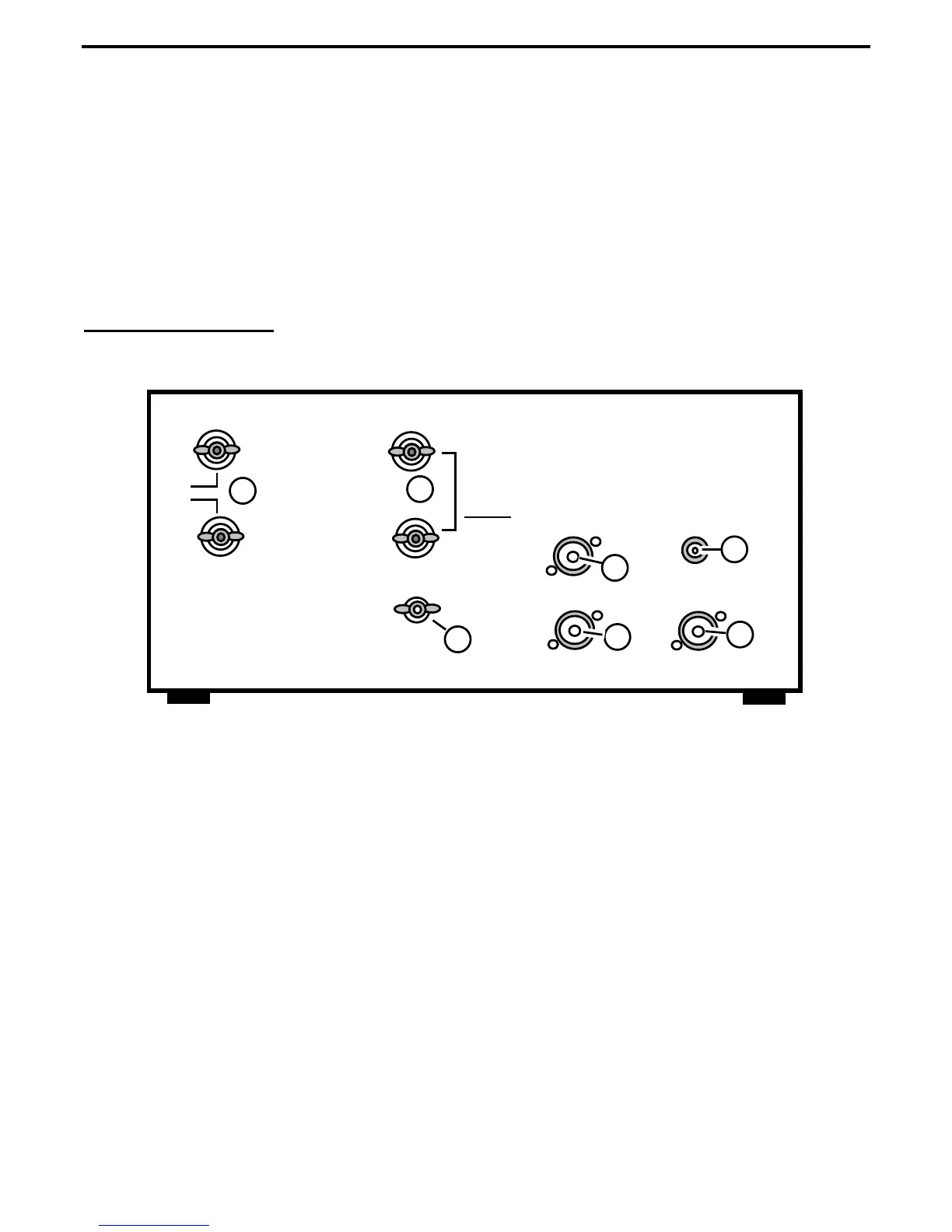
Rear Panel Layout
6
1
2
COAX-1
COAX-2
METER LAMP
TRANSMITTER
GND
BAL LINE
WIRE
Install Jumper For
Balanced Line
Operation
12V DC
<
5
4
3
7
1. Meter Lamp: 2.1-mm coaxial power jack accepts 12 vdc to operate the LED meter lamps and the
metering circuit (see text)
2. Transmitter: Accepts PL-259, connects transceiver or amplifier to tuner.
3. Coax-1: Accepts PL-259, connects antenna #1 to tuner routing switch.
4. Coax-2: Accepts PL-259, connects antenna #2 to tuner routing switch.
5. GND: Chassis ground, connects tuner to station's ground system.
6. Bal Line: Antenna side of the 1:1 balun, accepts balanced feedlines.
7. Wire: terminal post (Wire) accepts single-wire antennas. To feed balanced antennas through the
balun, the Wire terminal is connected to the terminal post below with a jumper (see text).