MFJ-941E Versa Tuner II
2
4. A random wire antenna may be connected to the five-way binding post marked WIRE. The
random length wire should be long, high, and as clear of surrounding objects as possible. For
optimum operation, the wire antenna should be a quarter wave-length or longer at the operating
frequency. Do NOT ground the random wire antenna. The tuner should be well-grounded to the
transmitter. A binding post marked GROUND is provided for ground connections.
5.
A balanced line-fed antenna may be connected to the two five-way binding posts marked
BALANCED LINE. A jumper wire from the WIRE binding post, as indicated by a dotted line
on the MFJ-941E, should be connected to one of the posts of the BALANCE LINE. This
couples the MFJ-941E to the balanced line through a 4:1 balun.
NOTE:
Either a balanced line or a random wire antenna may be connected to the MFJ-941E at one
time. If a random length wire is used, care should be taken to assure that no jumper wire is
between the WIRE binding post and the BALANCED LINE.
6. An external 50 Ohm dummy load may be connected to the EXT. DUMMY LOAD connector
located at the rear of the tuner.
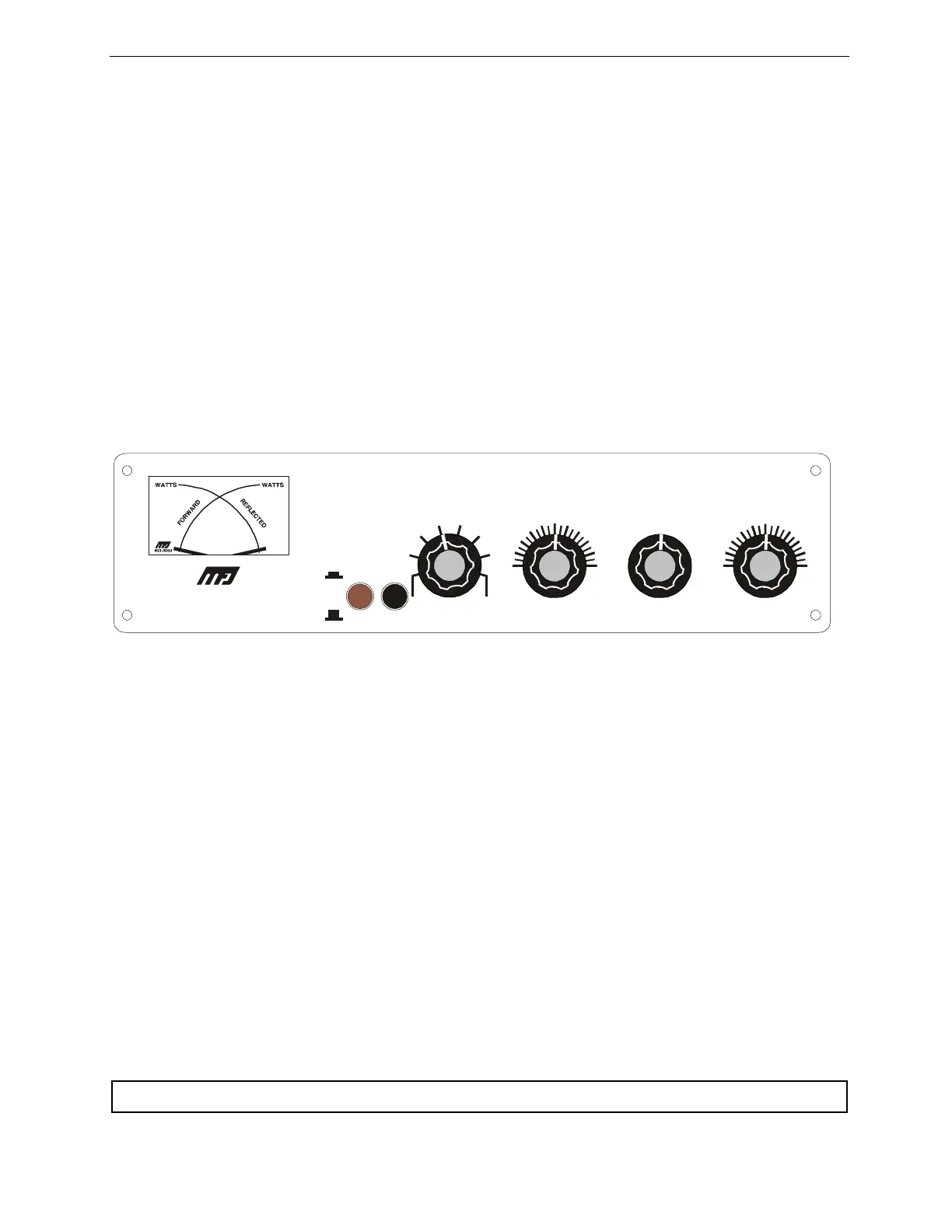
MFJ-941E FRONT PANEL
10
MATCHING
ANTENNA
MATCHING
INDUCTOR
SELECTOR
J
K
L
A
B
C
D
E
F
G
H
I
ANTENNA
SELECTOR
ON
POWER
OFF
300W
30W
MODEL MFJ-941E
LAMP
BAL.
LINE
WIRE
BAL.
LINE
WIRE
EXT.
LOAD
EXT.
LOAD
COAX 1COAX 1
COAX 2COAX 2
TUNED BYPASS
USING THE MFJ-941E
The INDUCTOR switch on the MFJ-941E represents maximum inductance at position "A" and the
minimum inductance at position "L". Lower inductance is needed at higher frequencies than at low
frequencies for the same impedance. The TRANSMITTER and ANTENNA controls represent
maximum capacitance at position 10. For optimum operation of the MFJ-941E, the transmitter must be
tuned to a 50 Ohm output impedance at the frequency of operation. The ANTENNA SELECTOR
switch should be set to DUMMY LOAD for tuning up the transmitter.
NOTE: The transmitter should always be tuned at a low output power.
After the transmitter is properly tuned, the ANTENNA SELECTOR should be set to the desired antenna
and the tuner adjusted for a minimum SWR as described below. DO NOT readjust the transmitter
loading control setting after loading it to 50 Ohms.
NOTE:
When using the MFJ-941E for receiving only, tune as described in Steps 1 and 2.
TUNER ADJUSTMENT
1. Set the TRANSMITTER and ANTENNA controls to 5. In this position the capacitors are half-
open.
2. Rotate the INDUCTOR control until maximum noise is obtained with the transceiver in the
receiving mode.
CAUTION: Do not operate the ANTENNA selector switch while transmitting!.