Electrical
FUSES
The fuses are housed in a fuse block (1) mounted in the engine
compartment
Fig
. 2 body adjacent to the battery.
Fuse
2 and 3 protects the side and tail lamps.
Fuse 4 protects the .circuits which operate only when the ignition switch is on,
viz. stop lamps, reverse lamps.
Fuse
5 protects the equipment which operates independently of the igniti on
switch, viz. horns, interior lamp, cigar-lighter.
Two spare fuses (6) are provided
and
it is important to use the correct replace-
ment fuse. The fusing value, current rated 17 amp.
(35 amp. blow rated), is
marked on a coloured slip of paper inside the glass tube of the fuse.
line
fuses
Auxiliary equipment. The 35 amp. line fuse (7) protects the windscreen wiper,
windscreen washer, heater blower motor and radio, which operate when the
ignition switch is in position
'
I'
.
Haza
rd warning. The 35 amp. line fuse (8) protects the hazard warning lamps .
Radio. A separate additional line fuse protects the radio (if fitted). See the
instructions supplied with the radio for ,the correct fuse ratings.
Blown
fuses
The units which are protected by the fuses can be identified from the wiring
diagram. A blown fuse is indicated by the failure of all the units protected by it,
and is confirmed by examination of the fuse when withdrawn.
Before renewing a blown fuse inspect the wiring of the units
that
have failed for
evidence of a short-circuit or other fault.
o
Fuse 5 pro tects the equipment which operates independently of the igniti on
switch, viz. horns, interior lamp, cigar-lighter.
Two spare fuses (6) are provided
and
it is important to use the correct replace-
ment fuse. The fusing value, current rated 17 amp .
(35 amp. blow rated), is
marked on a coloured slip of paper inside the glass tube of the fuse.
line
fuses
Auxiliary equipment. The 35 amp . line fuse (7) protects the windscreen wiper,
windscreen washer, heater blower motor and radio, which operate when the
ignition switch is in position
'I'
.
Accesso
rie s
If
an electrical accessory is being fitted and is required to operate irrespective of
the ignition circuit it should be connected to terminal 5 on the fuse block; if it is
required to operate only when the ignition is switched on, connect to terminal 4.
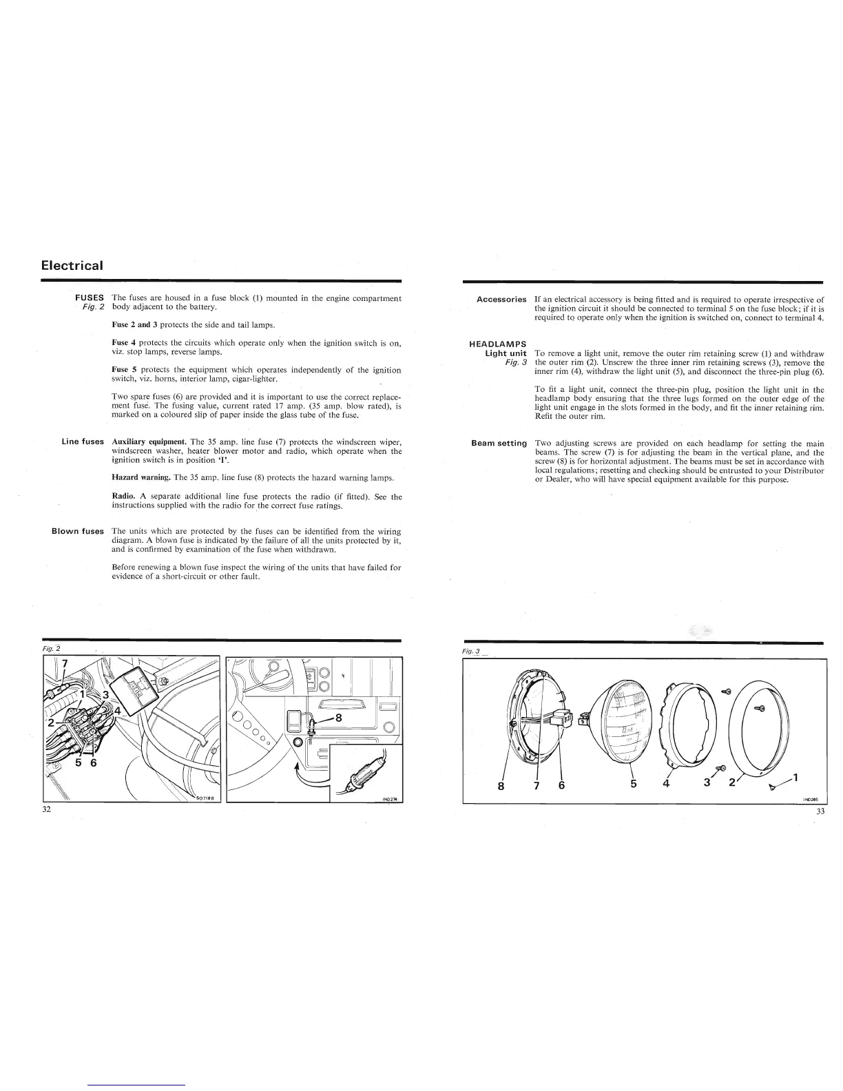
HEADLAMPS
light
un
it
To remove a light unit, remove the outer rim retaining screw (1) and withdraw
Fig
.3
the outer rim (2). Unscrew the three inner rim retaining screws (3), remove the
inner rim (4), 'withdraw the light unit (5), and disconnect the three-pin plug (6).
To fit a light unit, connect the three-pin plug, position the light unit in the
headlamp body ensuring
that
the three lugs formed on the outer edge of the
light unit engage in the slots formed in the body, and fit the inner retaining rim.
Refit the outer rim.
Bea
m
sett
ing
Two adjusting screws are provided on each headlamp for setting the
main
beams. The screw (7) is for adjusting the beam in the vertical plane, and the
screw (8) is for horizontal adjustment. The beams must be set in accordance with
local regulations; resetting and checking should be entrusted to your Distributor
or Dealer, who will have special equipment available for this purpose.
n
4lll(@
(A
----r--
', ',,
CIZl@
_
._~
',' (
-6
:".' 1
the outer rim (2). Unscrew the three inner rim retaining screws (3), remove the
inner rim (4), 'withdraw the light unit (5), and disconnect the three-pin plug (6).
To fit a light unit, connect the three-pin plug, position the light unit in the
headlamp body ensuring
that
the three lugs formed on the outer edge of the
light unit engage in the slots formed in the body, and fit the inner retaining rim.
Refit the outer rim.
Beam
setting
Two adjusting screws are provided on each headlamp for setting the
main
beams. The screw (7) is for adjusting the beam in the vertical plane, and the
screw (8) is for horizontal adjustment. The beams must be set in accordance with
1_
........1
._
1
_.L
~ •
_~
.L
.L':
..J
_1
1
_
~ 1
1..11
.-
.Lu
~
_ _' J _ _ _
,........
• • " 1_ •
 Loading...


