INDlViDUAL
BRAKE
ADJUSTING
NUT
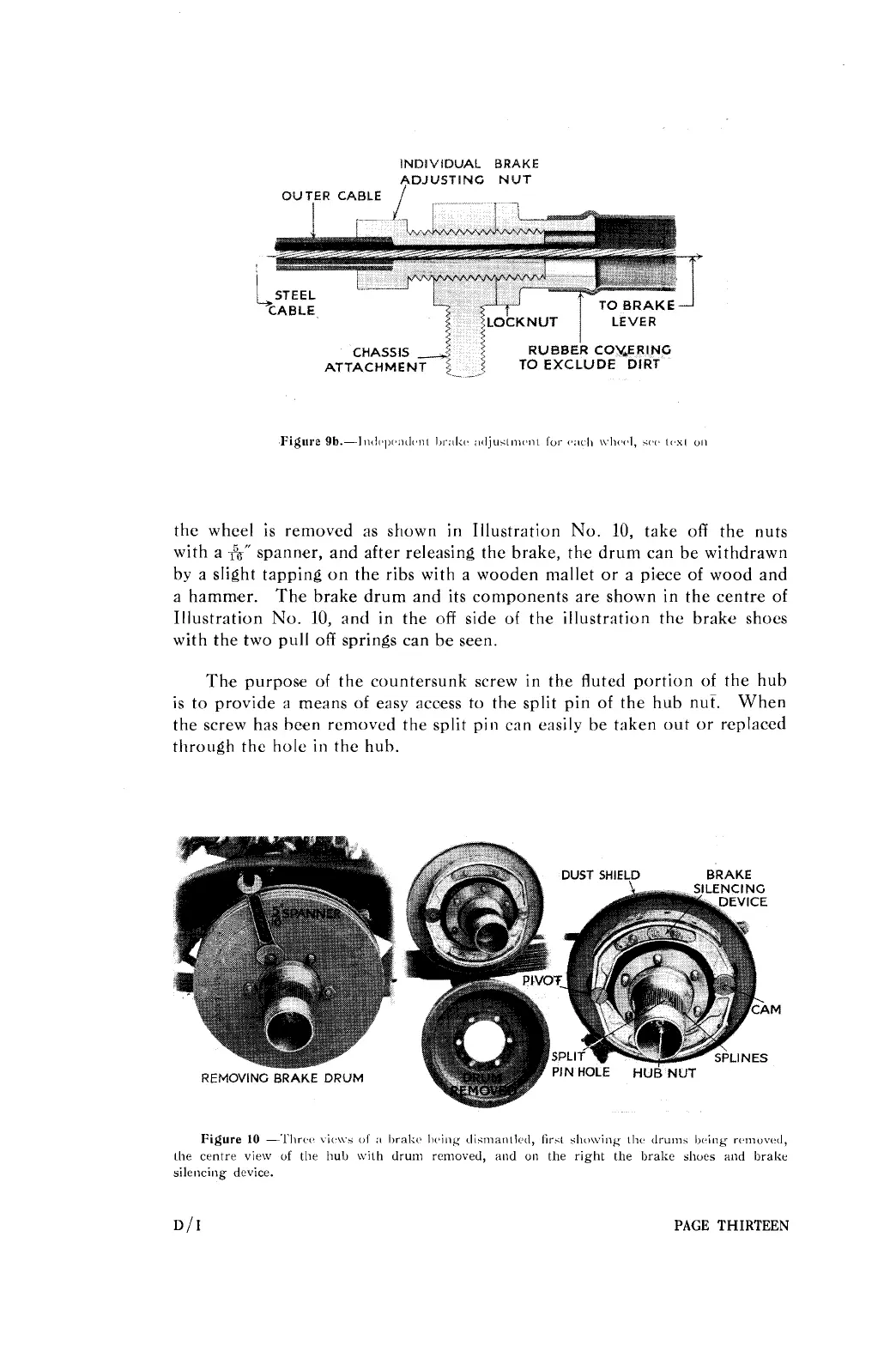
the wheel is removed as shown in Illustration No.
10,
take off the nuts
with a
h''
spanner, and after releasing the brake, the drum can be withdrawn
by a slight tapping on the ribs with a wooden mallet or a piece of wood and
a hamm'er. The brake drum and its components are shown in the centre of
Illustration No.
10,
and in the off side of the illustration the brakre shoes
with the two pull off springs can be seen.
The purpose of the countersunk screw in the fluted portion of the hub
is to provide
a
means of easy acoess to the split pin of the hub nut.
When
the screw has been removed the split pin can easily be taken out or replaced
through
the hole in the hub.
REMOVING
BRAKE
DRUM
DUST
SHIELD BRAKE
SILENCING
h
DEVICE
Figure
l0
-'l%rc~(~ \ic,\vs
elf
:I
l)ralw Ix~ing diwientlc~cl, lirit sIio\ving tlic, dru~ii.
l~c,i~ig
rcmiuv(d,
[he centre view of the hub \vilh drum removed, end
on
the right the brake shoes end brake
silencing device.
PAGE
THIRTEEN