Do you have a question about the MGE UPS Systems Comet EX 11 RT 3:1 and is the answer not in the manual?
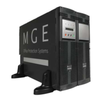
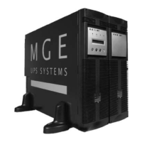
Details standard configurations for Comet EX RT UPS, including tower and rack mounting options.
Details dimensions and weight for tower configuration.
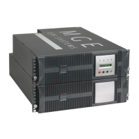
Details dimensions and weight for rack configuration.
Description of the rear panel connectors and components for the power and battery modules.
Identifies ports and connectors on the power module's rear panel.
Identifies connectors and breakers on the battery module's rear panel.
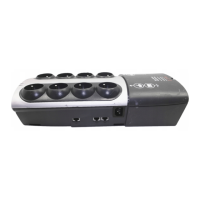
Overview of the front panel display and control buttons of the UPS.
Overview of the UPS front panel display and control buttons.
Details optional accessories and configurations for the UPS, such as rack mounting kits.
Description and part numbers for rack mounting hardware.
Information on the transformer module for isolation or earthing changes.
Information on the transformer module for isolation or earthing changes.
How to extend UPS backup time with additional battery modules.
How to extend UPS backup time with additional battery modules.
Information on the CLA module for 2-8 hours backup.
Information on the CLA module for 2-8 hours backup.
System for integrating up to 8 modules for extended backup.
System for integrating up to 8 modules for extended backup.
Details the battery module with Remote Emergency Power Off function.
Details the battery module with Remote Emergency Power Off function.
Description of the 1.8m/6ft battery extension cable.
Description of the 1.8m/6ft battery extension cable.
Instructions for unpacking and checking the contents of the power and battery modules.
List of components included with the power module upon unpacking.
List of components included with the battery module upon unpacking.
Step-by-step guide for installing the UPS in a tower configuration.
Step-by-step guide for installing the UPS in a tower configuration.
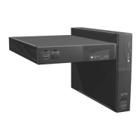
Instructions for installing the UPS in a rack configuration.
Guide on adjusting the UPS front panel orientation for rack mounting.
Detailed steps for mounting the battery module into a rack.
Instructions for mounting UPS modules onto rack rails.
Instructions for mounting UPS modules onto rack rails.
Description of the rear bracket system for moving rack-mounted UPS units.
Description of the rear bracket system for moving rack-mounted UPS units.
Bracket for the input/output box aiding hot-swapping of power modules.
Bracket for the input/output box aiding hot-swapping of power modules.
Overview of the UPS communication methods: RS232, relays, and communication cards.
Instructions for connecting the UPS via RS232 to a computer.
Explanation of the relay communication port and its pin assignments.
Details the REPO communication port for emergency power off.
Details the REPO communication port for emergency power off.
Steps for installing optional communication cards into the UPS.
Steps for installing optional communication cards into the UPS.
Guides installation based on different system earthing arrangements.
Diagrams for connecting UPS with common Normal and Bypass AC inputs.
Diagrams for connecting UPS with separate Normal and Bypass AC inputs.
Diagrams for connecting UPS with separate AC inputs from different sources.
Diagrams for connecting UPS with separate AC inputs from different sources.
Configuration for using the UPS as a frequency converter.
Configuration for using the UPS as a frequency converter.
Configuration for providing full redundancy (N+1) to critical loads.
Configuration for providing full redundancy (N+1) to critical loads.
Recommendations for upstream/downstream circuit breakers and cable specifications.
Table of circuit breaker recommendations for upstream protection.
Table of circuit breaker recommendations for downstream protection.
Specifications for terminal-block and earthing conductor cable capacity.
Detailed instructions for connecting input/output power cables for various configurations.
Guide for connecting power cables with common AC sources.
Guide for connecting power cables with separate AC sources.
Guide for connecting power cables with separate AC sources.
Instructions for connecting power cables for frequency converter use.
Instructions for connecting power cables for frequency converter use.
Instructions for connecting the battery power and detection cables.
Instructions for connecting battery power and detection cables.
Diagram and specifications for connecting a galvanic isolation transformer.
Diagram and specifications for connecting a galvanic isolation transformer.
Instructions for connecting the CLA module to power and battery.
Instructions for connecting the CLA module to power and battery.
Procedure for the initial startup of the UPS and its personalization.
Explanation of UPS personalization via front panel or software.
Steps to enter personalization mode using front panel buttons.
Configuration options for language, date/time, and audible alarm.
Details output voltage, frequency converter, eco mode, and hot standby settings.
Configuration options for UPS power management and battery features.
Configuration options for UPS power management features.
Settings for battery test, low battery, runtime, and discharge protection.
Instructions for personalizing the UPS using the Personal Solution-Pac software.
Instructions for personalizing the UPS using the Personal Solution-Pac software.
Steps for the final startup sequence, including LED indicators.
Steps for the final startup sequence, including LED indicators.
Description of the Normal (double conversion) and Eco operating modes.
Explains the normal operating mode, load protection, and measurements.
Details the Eco mode, its advantages, and operating conditions.
Information on how the UPS operates when the normal AC source is unavailable.
Describes the transition to battery power and related indicators.
Details the low-battery warning indication and its implications.
Explains status when backup time is exhausted and load transfer.
Procedure for when the normal AC source is restored after an outage.
Procedure for when the normal AC source is restored after an outage.
Step-by-step instructions for shutting down the UPS and loads.
Step-by-step instructions for shutting down the UPS and loads.
Guides for identifying and resolving common UPS operating anomalies and alarms.
Common issues and solutions not requiring external support.
Issues that require contacting the after-sales support department.
Procedure for replacing the power module without interrupting the load.
Steps to safely disconnect the power module for replacement.
Steps to reconnect the power module after replacement.
Steps to reconnect the power module after replacement.
Procedure for replacing the battery module without interrupting UPS operation.
Steps to safely disconnect the battery module for replacement.
Steps to reconnect the battery module after replacement.
Steps to reconnect the battery module after replacement.
Information on technical training courses offered by MGE UPS SYSTEMS.
Information on technical training courses offered by MGE UPS SYSTEMS.
Detailed electrical characteristics and protection device selection for the UPS.
Provides electrical specifications for I/T and industrial operating modes.
Guides on selecting upstream and downstream protection devices.
Graphical representations of time/current curves for UPS components.
Graphical curves for the AC source circuit-breaker.
Graphical curves for UPS input and output fuses.
Various UPS characteristics including input/output data, voltage, and overload graphs.
Table detailing voltage and frequency characteristics for UPS input/output.
Graph showing power supplied relative to input voltage.
Graph illustrating permissible UPS overload capacity over time.
Specifications for short-circuit current capabilities in Normal or Battery mode.
Technical specifications for the Comet EX Transformer module.
Specifications and configuration details for the Comet EX RT CLA module.
Specifications and configuration details for the Comet EX RT CLA module.
Information on operating temperature and its effect on UPS performance.
Information on operating temperature and its effect on UPS performance.
Definitions of key terms used throughout the UPS manual.
Definitions of key terms used throughout the UPS manual.
| Battery Type | Sealed Lead-Acid (SLA) |
|---|---|
| Waveform | Sinewave |
| Operating Temperature | 0 - 40 °C |
| Power Rating | 11 kVA |
| Topology | Double Conversion |
| Output Voltage | 230 V |
| Input Frequency | 50/60 Hz |
| Output Frequency | 50/60 Hz |
| Form Factor | Tower |
| Capacity | 11 kVA / 8.8 kW |
| Communication Interface | RS-232, USB, SNMP (Optional) |