MGE UPS SYSTEMS - 5102761700/AC
24
Fig. 8
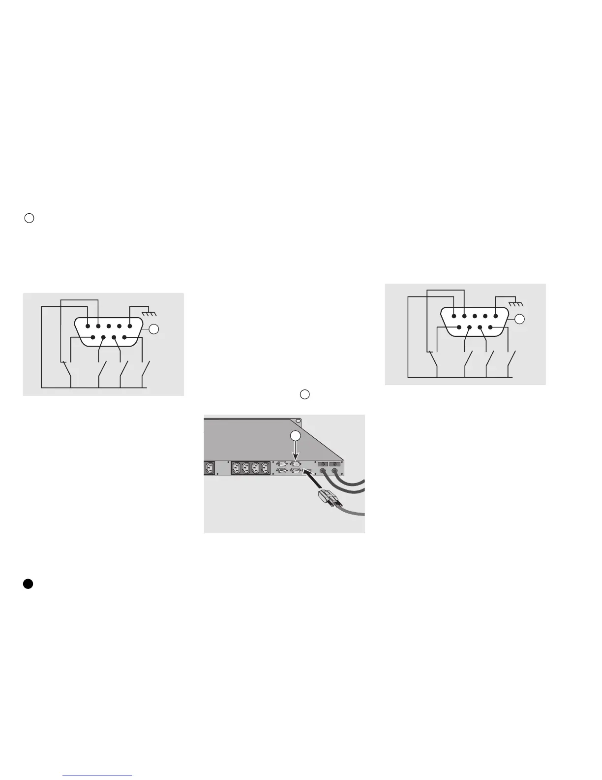
The pin-out of the Basic Pulsar STS port
12 is the following:
◗ pin 1 – frame earth,
◗ pin 4 – normal operation,
◗ pin 5 – common,
◗ pin 6 – operation on bypass,
◗ pin 7 – low battery shutdown warning,
◗ pin 8 – operation on inverter,
◗ pin 9 – operation on battery.
Fig. 10
Fig. 9
12
NO
NC
NO NONO
5432
1
9
876
common
UPS with "Protocol
Interface" (option)
This option converts Basic type information
into the RS232 serial protocol. It is then
possible to use the administration and
system shutdown capabilities of Solution
Pac software.
Pulsar STS
STS COM
13
Breaking capacity of relays:
V max = 30 V
I max = 100 mA
NO = normally open,
NC = normally closed.
MultiSlot (optional)
When the MultiSlot option is installed, the
Pulsar STS and the two UPSs act as a one.
MultiSlot, equipped with two MetaUPS
acquisition cards, concentrates the data
coming from the U-Talk ports on the UPSs
and from the STS COM port on Pulsar STS.
Communication with the protected systems
is optimized through use of a U-Talk, J-Bus
or SNMP card.
In this case, the protected application will
shutdown only when all available energy has
disappeared, i.e. the batteries on both UPSs
have been depleted. See the MultiSlot user
manual for information on connections.
STS COM communication
This communications port 13 supplies
status information on Pulsar STS.
Pin-out of the STS COM port:
◗ pin 1 – frame earth,
◗ pin 4 – source S2 preferred,
◗ pin 5 – common,
◗ pin 6 – source S1 within tolerances,
◗ pin 7 – source S2 within tolerances,
◗ pin 8 – no fault in Pulsar STS,
◗ pin 9 – source S1 preferred.


 To Next Page