Procon
. S T
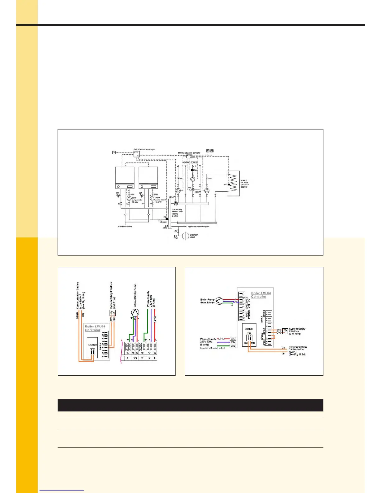
Typical multiple Procon , , & boiler installation utilizing an RVA Cascade Manager and a RVA
Controller, two heating zones, one of which having mixing valves, and domestic hot water with individual charg-
ing pumps, using a low velocity mixing header. RVA Controller & Housing, an RVA Controller & Housing,
No QAD/ ow sensors, and OCI Communication Clip-In Modules ( per boiler) required.
Please note;
• The Procon, & models include an internal pump and therefore an external boiler pumpis
not required.
• The wiring of the internal pump on the Procon MUST be relocated from K (Terminals &)
to K (Terminals & )
• The boiler pump on the Procon must be wired to K (Terminals X-)
Essential Boiler Parameter Changes Applicable to System Type .
Line ID Description
Default
Setting
New Setting for
This System
H Summer/Winter Changer Over
H Hydraulic System Con guration
{ & }
{ & }
H
Boiler Numbering In Cascade
{ = Boiler No, = Boiler No, = Boiler No,… = Boiler
No}
–
Fig .a – Hydraulic Layout
Fig .b – Wiring Diagram for Models , &
Fig .c – Wiring Diagram for Model
Legend
C & Heating Zone & Temp
Controllers ( Per Zone re-
quired either QAA, QAA
or QAA) or Volt Free En-
able.
OS Outside Air Sensor (QAC)
or
Ω Resistor {Fitted to
RVA}
SV Safety Valve.
IV Isolation Valve
LSV Lockable Service Valve
S/T Hot Water Sensor (QAZ), or
Volt Free Enable
CWM Cold Water Main
DOC Drain O Cock
NRV Non-Return Valve
RVA Kascade Manager
FS Flow Sensor (QAD/)
RS Return Sensor (QAD/)
ZFS Zone Flow Sensor (QAD)
 Loading...