Procon
. S T
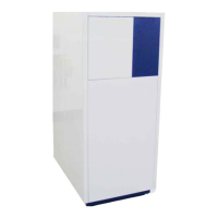
Typical single Procon , , & boiler installation utilizing an AGU. Clip-In Module serving two heat-
ing zones, one with a mixing valve, and domestic hot water (priority) with individual charging pumps, using a
low velocity mixing header. AGU. Clip-In Module and QAD ow sensor required.
Please note;
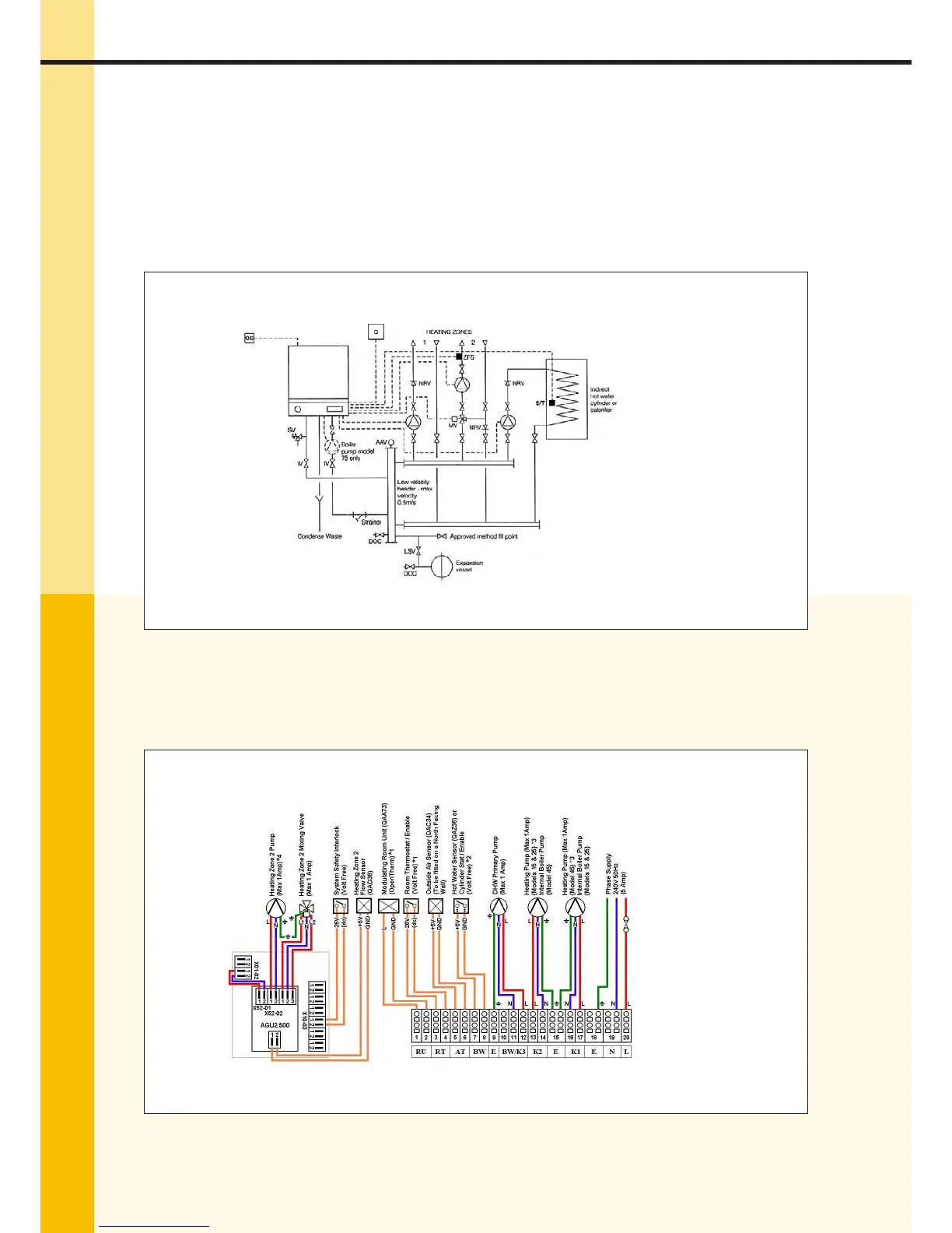
• The Procon, & models include an internal pump and therefore an external boiler pump is
not required.
• The boiler pump on the Procon must be wired to K (Terminals X-)
Fig .a – Hydraulic Layout
Fig .b – Wiring Diagram for Models , &
Legend
C External Controller, either
QAA Room Unit, or Volt
Free Enable.
OS Outside Air Sensor (QAC)
SV Safety Valve
IV Isolation Valve
LSV Lockable Service Valve
S/T Hot Water Sensor (QAZ), or
Volt Free Enable
CWM Cold Water Main
DOC Drain O Cock
ZFS Zone Flow Sensor (QAD)
Notes
* Only t one type of Room
Temperature Control.
* Parameter Change may be
required.
* Heating Zone
* Heating Zone , via AGU.
Clip-In Module.
 Loading...