Update Documentation P341/EN AD/F43
MiCOM P341
(AD) -21
Non-Directional
Directional Fwd
Directional Rev
IN1>3 Current Set: 0.08…32.00 In
IN1>3 Time Delay: 0.00…200.00s
IN1>4 as IN>3
IN1> Blocking:
Binary function link string, selecting which
ground overcurrent elements (stages 1 to 4)
will be blocked if VTS detection of fuse
failure occurs.
IN1> Char Angle: -95… +95
o
IN1> Polarization:
Zero Sequence
Neg. Sequence
IN1> VNpol Set:
0.5…80.0V (100/110V)
2…320V (380/480V)
IN1> V2pol Set:
0.5…25.0V (100/110V)
2…100V (380/480V)
IN1> I2pol Set: 0.08…1.00 In
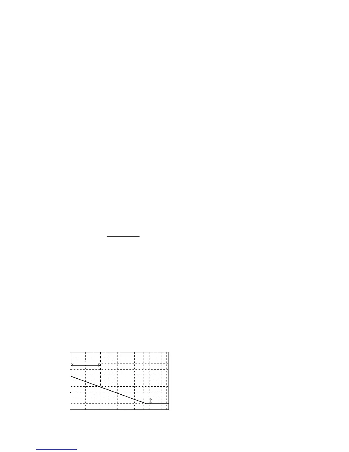
The IDG curve is commonly used for time
delayed earth fault protection in the Swedish
market. This curve is available in stage 1 of
the Earth Fault protection.
The IDG curve is represented by the following
equation:
t = 5.8 - 1.35 log
e
N > Setting
in seconds
Where:
= Measured current
N>Setting = An adjustable setting which
defines the start point of the
characteristic
Although the start point of the characteristic is
defined by the “N>” setting, the actual relay
current threshold is a different setting called
“IDG s”. The “IDG s” setting is set as a
multiple of “N>”.
An additional setting “IDG Time” is also used
to set the minimum operating time at high
levels of fault current.
0
1
2
3
4
5
6
7
8
9
10
110100
I/IN>
Operating time (seconds)
IDG Is Setting Range
IDG Time Setting Range
P2242ENa
IDG Characteristic
SEF/REF Prot’n
SEF/REF Options:
SEF
SEF Cos (PHI)
SEF Sin (PHI)
Wattmetric
Hi Z REF
ISEF>1 Function:
Disabled
DT
IEC S Inverse
IEC V Inverse
IEC E Inverse
UK LT Inverse
RI
IEEE M Inverse
IEEE V Inverse
IEEE E Inverse
US Inverse
US ST Inverse
IDG
ISEF>1 Directional:
Non-Directional
Directional Fwd
Directional Rev.
ISEF>1 Current Set: 0.005...0.10 In
ISEF>1 IDG Is: 1.0...4.0 In
ISEF>1 Time Delay: 0.00...200.00s
ISEF>1 TMS: 0.025...1.200
ISEF>1 Time Dial: 0.01...100.0
ISEF>1 IDG Time: 1.00...2.00
ISEF>1 Reset Char: DT/Inverse
ISEF>1 tRESET: 0.00...100.00s
ISEF>2 as ISEF>2
ISEF>3 Status:
Disabled
Enabled
ISEF>3 Directional:
Non-Directional
Directional Fwd
Directional Rev
ISEF>3 Current Set: 0.005...0.80 In
ISEF>3 Time Delay: 0.00...200.00s
ISEF>4 as ISEF>3
ISEF> Blocking:
Binary function link string, selecting which
ground overcurrent elements (stages 1 to 4)
will be blocked if VTS detection of fuse
failure occurs.
ISEF> Char. Angle: -95...+95 o
ISEF> VNpol Set:
0.5...80.0V (100/120V)
2...320V (380/480V)
WATTMETRIC SEF:
PN> Setting: 0....20In W (100/120V)
PN> Setting: 0 ....80In W (380/480V)