Familiarization with RM1200 Equipment
1 kW PA Front Panel
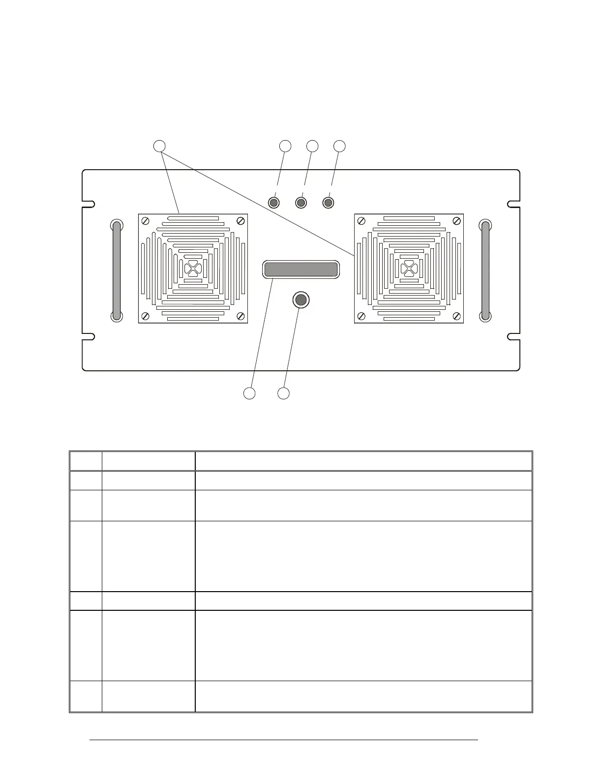
Figure 9 identifies the items located on the front panel of the 1 kW amplifier, and Table 3 explains
their functions.
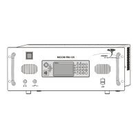
RM-1200 FAULT BYPASS 1000HF SSB - AMPLIFIERTX
DISPLAY MODE
65
12
43
Figure 9. 1 kW PA Front Panel
Table 3. 1 kW PA Front Panel Items
Item Description Function
1 Display LCD display. See the following section for displayed information
2 DISPLAY MODE
push-button
Selects the type of information presented on the display
3 BYPASS indicator Lights when the 1 kW amplifier is in the bypass mode (in this mode, the RF IN
connector is directly connected to the RF OUT connector).
The 1 kW amplifier is normally bypassed when the radio is in the receive mode.
It is also bypassed when it is not powered, or a fault or abnormal condition
prevents its normal operation
4 TX indicator Lights when the 1 kW amplifier is switched to the transmit mode
5 FAULT indicator Lights when a fault in the 1 kW amplifier does not allow normal operation. In
this case, the amplifier remains in the bypass mode until the fault is corrected.
Flashes when an operational problem, for example, high temperature or
excessive VSWR, activates the corresponding protection circuits and causes the
amplifier to reduce its output power or temporarily switch to the bypass mode
6 Air intake vents Intake vents for cooling air, with removable covers that provide access to the
dust filters
24 6888882V02