Familiarization with Equipment
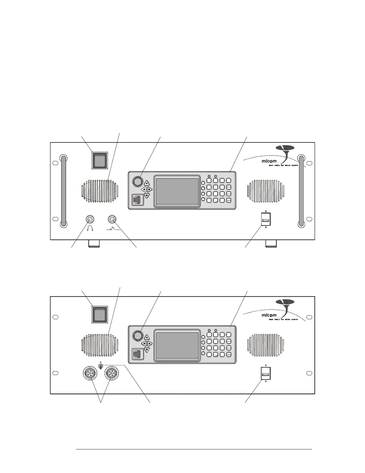
Front Panels
The front panels of the RM125 and RM125R include a standard MICOM-3 control panel and the
additional items identified in Figure 3, respectively Figure 4.
For a description of the MICOM-3 control panel, refer to the “Owner’s Guide, MICOM-3E/3T/3R
HF-SSB Transceivers”, Publication 6886867J01.
MICOM RM-125
USB
MICOM- 3
1
?
@
/
P
R
S
7
*
Q
JM
KN
LO
56
T
U
V
89
A
D
BE
C
F
23
0
#
Y
W
Z
X
MENU
Esc
P
GPS
ALAR M
F1
F2
F4
F3
G
H
I
4
Connector for Optional
External USB Keyboard
Headphone
Jack
Telegraphy Key
Jack
Internal Speaker
Standard MICOM-3
PanelControl
AC Power
ON/OFF Switch
ON/OFF & Volume Control
Turns transceiver on and off
and controls the speaker volume
Figure 3. RM125 Front Panel
MICOM RM-125R
USB
AUDIO
Connector for Optional
External USB Keyboard
Audio Connectors for
External Speaker
and Handset
Internal Speaker
ON/OFF Switch
MICOM-3
1
?
@
/
P
R
S
7
*
Q
J
M
KN
LO
56
T
U
V
89
A
D
BE
CF
23
0
#
Y
W
Z
X
MENU
Esc
P
GPS
ALAR M
F1
F2
F4
F3
G
H
I
4
Internal Speaker
Standard MICOM-3
PanelControl
AC Power
ON/OFF Switch
ON/OFF & Volume Control
Turns transceiver on and off
and controls the speaker volume
Figure 4. RM125R Front Panel
6888882V02 9