Bedienungsanleitung / Instruction Manual
colorSENSOR LT-1-ST - 2 -
1
E
l
e
k
t
r
i
s
c
h
e
A
n
s
c
h
l
ü
ss
e
/
E
l
ec
t
r
i
c
a
l
i
n
t
e
r
f
a
ce
s
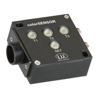
Die elektrischen Anschlüsse des Sensors zeigt Fig. 1./
The electrical connections of the sensor show Fig. 1.
Fig. 1 Elektrische Anschlüsse am Sensor/ Electrical interfaces
T
a
b
.
1
Bedeutung der
S
i
g
n
a
l
e
an Sensorbuchse
S
B
1
/
Sensor connector
S
B
1
pin
d
e
s
c
r
i
p
t
i
on
Schaltausgang (Kanal) 1/ Switching output (Channel) 0
Schaltausgang (Kanal) 2/ Switching output (Channel) 1
Einspeisung eines Triggerimpulses zur ext. Synchronisation/
trigger signal input for external synchronization purposes
1. Eingang zur Aktualisierung der Sensorausgänge (steigende
Flanke) im „EXTERN“ Modus/
input for updating the sensor outputs (rising edge) in “EXTERN”
mode
2. Eingang für Triggergesteuerte Farbsequenz im „TRIGG. SEQU.“
Modus (steigende Flanke)/
input for trigger controlled color sequence in “TRIGG. SEQU.”
mode (rising edge)
3. Eingang für zeitgesteuerte Farbsequenzerkennung im „TIMED
SEQU.“ Modus (steigende Flanke)/
input for starting timed color sequence in “TIMED SEQU.” mode
(rising edge)
4. Eingang für externes Teach-In im „EXT. TEACH“ Modus
(steigende Flanke)/
input for external triggered Teach-In in “EXT. TEACH” mode
(rising edge)
Schaltausgang (Kanal) 4/ Switching output (Channel) 4
Ausgang zur Synchronisation einer externen Zusatzbeleuchtung
oder weiterer Sensoren/
output signal for synchronization of an additional external light
source or an additional sensor
Ausgang für allgemeine Zwecke/ General purpose output
Schaltausgang (Kanal) 3/ Switching output (Channel) 3
Betriebsspannung/ Power supply
2
T
ec
h
n
i
s
c
h
e
Daten/
T
ec
hn
i
c
a
l
D
a
t
a
T
a
b
.
2 Allgemeine
Daten/
G
e
n
e
r
a
l
d
a
t
a
Fotodetektor/ Photo detector
Dreibereichsfotodiode/ Three range photo diode
A/D Umsetzung/ A/D conversion
Fremdlichtkompensation/ Ambient light
compensation
Dynamisch, Abschaltbar/ Dynamic, can be switched
off
Objektbeleuchtung/ Object illumination
Weißlicht-LED/ White light LED
Abschaltbar/ Can be switched off
RS232 (max. 115 kBit/s)
4 Schaltausgänge/ 4 switching outputs