Do you have a question about the MICRO-EPSILON thermoMETER CT Series and is the answer not in the manual?
Explanation of safety symbols used in the manual.
Critical safety warnings for device operation and handling.
Information regarding CE conformity and relevant EU directives.
Specifies the intended applications and limitations of the thermoMETER CT.
Details environmental conditions for optimal sensor and controller operation.
Guidelines for safe use of optional laser sighting tools.
Explains how the infrared sensors measure temperature.
Overview of different thermoMETER CT sensor models and their specifications.
Lists general technical details for sensors and controllers.
Details power supply, outputs, and interface specifications.
Provides detailed measurement parameters for various sensor models.
Instructions for unpacking the sensor and controller components.
Guidelines for proper storage of the device.
Explains how to read optical charts and spot size ratios.
Information on installing sensors using threads and mounting brackets.
Details pin assignments for various sensor models.
Requirements for the power supply unit.
Instructions for preparing and assembling sensor cables.
Procedures for managing ground connections to prevent interference.
Steps for replacing a sensor and entering calibration codes.
Configuration of analog output channels for temperature data.
Overview of optional digital communication interfaces.
Details on optional relay outputs for alarm functions.
Configuration of programmable functional inputs (F1-F3).
Features related to alarm settings, visual indicators, and outputs.
Procedure to reset the device to its default factory settings.
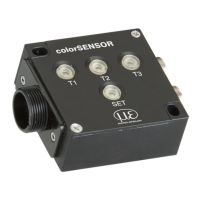
On-site configuration of sensor parameters using programming keys.
Detailed descriptions of the device's menu items and settings.
Lists and explains common error messages displayed by the sensor.
Guidelines for cleaning the sensor lens and housing.
Minimum system specifications for installing CompactConnect software.
Highlights key functionalities of the CompactConnect software.
Configuration settings for serial communication.
Information on the binary and ASCII protocols used.
How to switch to and use the ASCII communication protocol.
How to save configuration changes to the sensor's memory.
Explains the fundamental concepts of infrared temperature measurement.
Defines emissivity and its importance in infrared thermometry.
Methods for determining the emissivity of a surface.
Factors influencing characteristic emissivity values.
Details warranty period and conditions for material defects.
Information on how to contact for service and repair.
Guidelines for safe decommissioning and disposal of the device.
Details on various mounting brackets and accessories.
Information on air purge collars for lens protection.
Details on optional CF lenses and protective windows.
Information on additional accessories like mirrors and adapters.
Default device settings provided at the time of delivery.
Table of typical emissivity values for various metals.
Table of typical emissivity values for non-metallic materials.
Explanation of the Smart Averaging function for signal smoothing.
| Brand | MICRO-EPSILON |
|---|---|
| Model | thermoMETER CT Series |
| Category | Accessories |
| Language | English |