Page 53
Outputs and Inputs
thermoMETER CT
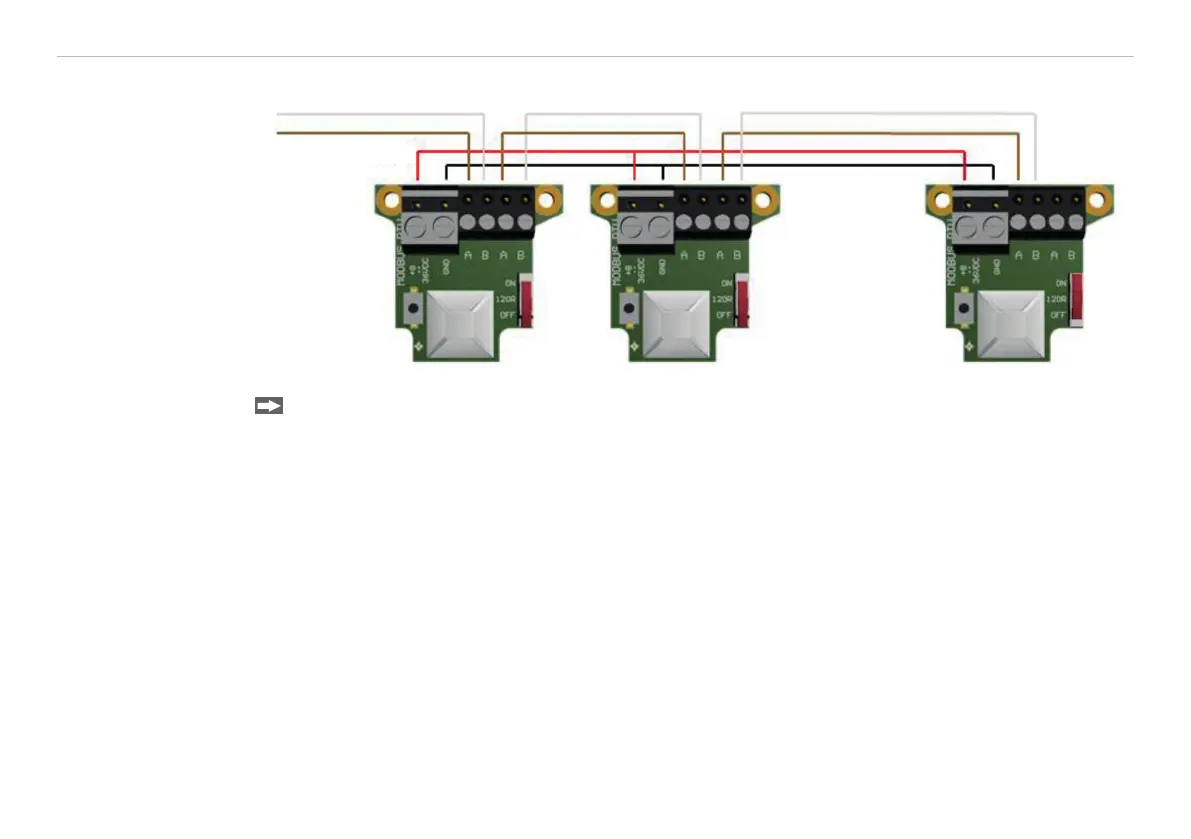
8.2.6.4 Connection of More than one Device (Synchronisation)
B
A
Modbus RTU 1 Modbus RTU 2 Modbus RTU n
8 - 36 V
Turn the 120R switch to ON for the last connected CT unit.
i
For the assignment of the Modbus ID of the individual devices, the devices must be connected one after
the other.
By default the Modbus ID is for every device 1.
In order to communicate, each device needs its own ID. The numbers 1 to 247 can be selected.
8.2.6.5 Overview of Digital Commands for Modbus RTU Digital Interfaces for CT and CTLaser
Sensors
The command overview is available online on the product side of the sensor at:
https://www.micro-epsilon.de/download/manuals/man--thermoMETER-ct-ctlaser-modbus-rtu-commands--en.
pdf

 Loading...


