Page 48
Outputs and Inputs
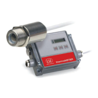
thermoMETER CT
8.2.5 CAN BUS Interface
Mount the CAN BUS adapter, see 8.2.
i
Make sure the wiring is correct, see Fig. 18.
i
We recommend for industrial installations to connect the shield of the CAN BUS cable with the control-
ler housing (inside the cable gland).
The thermoMETER CT always needs an external power supply.
CAN Protocol
CAN open (see documentation on CompactConnect software CD)
Wiring
CAN Bus:
CAN_H on terminal „H“
CAN_L on terminal „L“
Analog signal:
Black cord on terminal „GND“
Red cord on terminal „OUT-mV“
The controller contains additional terminals to connect other devices (power supply, CAN bus, terminating
resistor).
CAN module factory settings
Module address: 20 (14 H)
Baud rate: 250 kBaud
Analog input: 0 … 10 V
Temperature range: 0 … 60 °C (2 decimal places)
Emission ratio: 0.970
i
The settings for “Analog output 0 … 10 V“ and “Temperature range 0 … 60 °C” on the CT sensor must
be identical with the CAN bus module values.

 Loading...