Page 46
Outputs and Inputs
thermoMETER CT
8.2.4 Profibus Interface
8.2.4.1 Installation
Mount the Profibus adapter, see Chap. 7.2.
i
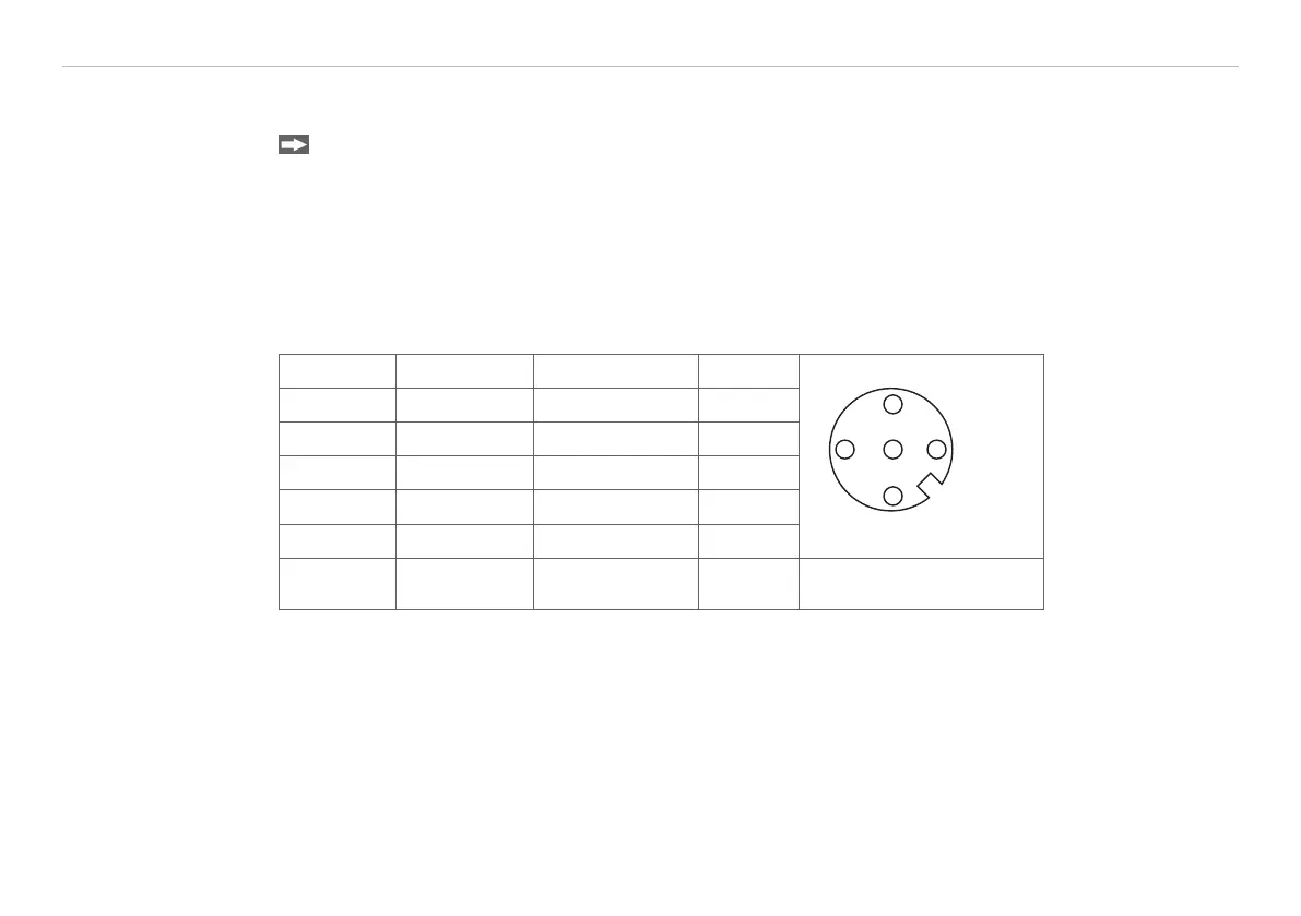
Make sure the wiring is correct, see Fig. 14.
i
We recommend for industrial installations to connect the shield of the Profibus cable with the controller
housing (inside the cable gland).
The thermoMETER CT always needs an external power supply.
Connector Color Function Pin
1
2
3
4
5
A Green A 2
B Red B 4
GND Blue Ground 3
VCC Brown +5 V (not used) 1
Shield n.c. 5
Housing Silver (shield) View on solder pin side
5-pin. round connector
1
Fig. 18 Pin assignment Profibus interface
1) Standard M12 Profibus round connector

 Loading...


