Page 66
Outputs and Inputs
thermoMETER CT
8.3 Relays Outputs
The thermoMETER CT can optionally be equipped with a relay output. The relay board is installed the same
way as the digital interfaces, see 8.2.
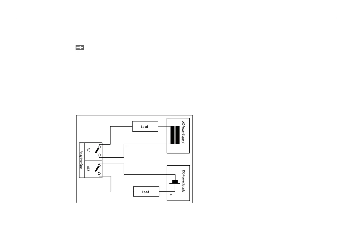
Connect the external electrical circuit with the terminal blocks.
A simultaneous installation of a digital interface and the relay outputs is not possible.
The switching thresholds correspondent with the values for alarm 1 and 2, see 8.5, see 3.5.2, and are factory-
set, see A 2.
Alarm 1 = 30 °C/ norm. Closed (Low-Alarm) and Alarm 2 = 100 °C/ norm. open (High-Alarm).
The adjustment of the alarms can result from the modification of the alarm 1 and alarm 2 via the program-
ming keys.
To make advanced settings (change of low- and high alarm) a digital interface (USB, RS232) and the Com-
pactConnect software is needed.
Fig. 25 Relay interface with pin assignment

 Loading...


