Page 40
Outputs and Inputs
thermoMETER CT
8. Outputs and Inputs
8.1 Analog Outputs
The thermoMETER CT has one or two analog output channels.
Please do never connect a supply voltage to the analog outputs. The thermoMETER CT is not a 2-wire sen-
sor!
> Destruction of output
8.1.1 Output Channel 1
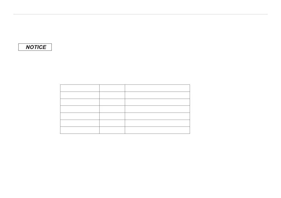
This output is used for the object temperature. The selection of the output signal can be done via the pro-
gramming keys, see 9. The CompactConnect software allows the programming of output channel 1 as an
alarm output.
Output signal Range Connection pin on CT board
Voltage 0 ... 5 V OUT-mV/mA
Voltage 0 ... 10 V OUT-mV/mA
Current 0 ... 20 mA OUT-mV/mA
Current 4 ... 20 mA OUT-mV/mA
Thermo couple TC J OUT-TC
Thermo couple TC K OUT-TC
i
According to the chosen output signal different connection pins on the main board are used
(OUT-mV/mA or OUT-TC).
8.1.2 Output Channel 2 (only CT-SF02, CT-SF15, CT-SF22, CTH, CTP-7 and CTP-3)
The connection pin OUT-AMB is used for output of the sensor temperature [-20 - 180 °C or -20 - 250 °C (on
CTH-SF02 and CTH-SF10) as 0 - 5 V or 0 - 10 V signal]. The CompactConnect software allows the program-
ming of output channel 2 as an alarm output. Instead of the sensor temperature THead also the object tem-
perature TObj or controller temperature TBox can be selected as alarm source.

 Loading...


