EasyManuals Logo

MICRO-EPSILON thermoMETER CT Series User Manual

MICRO-EPSILON thermoMETER CT Series
110 pages
To Next Page IconTo Next Page
To Previous Page IconTo Previous Page
Page #69 background imageLoading...
Page #69 background image
Page 69
Outputs and Inputs
thermoMETER CT
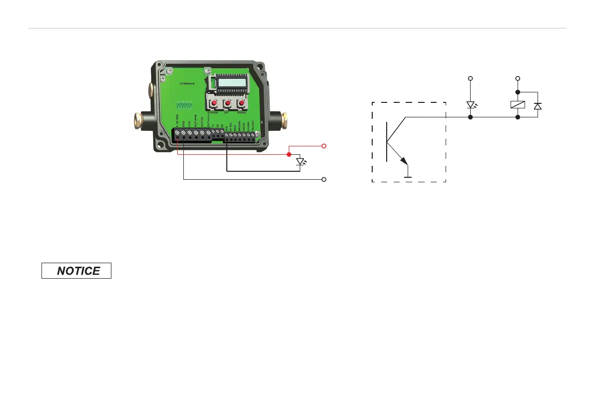
8.5.3 Open Collector Output / AL2
+24 V
GND
+24 V +24 V
GND
AL 2
CT / CTlaser LED Relais
Fig. 26 Open collector output / AL2 Fig. 27 Open collector output / AL2 circuit
diagram
i
The transistor acts as a switch. In case of alarm, the contact is closed.
A load/consumer (relay, LED or a resistor) must always be connected.
The alarm voltage (here 24 V) must not be connected directly to the alarm output (short circuit).
Avoid exceeding the maximum load of 50 mA on the output.
> Destruction of the output

Table of Contents

Questions and Answers:

Question and Answer IconNeed help?

Do you have a question about the MICRO-EPSILON thermoMETER CT Series and is the answer not in the manual?

MICRO-EPSILON thermoMETER CT Series Specifications

General IconGeneral
BrandMICRO-EPSILON
ModelthermoMETER CT Series
CategoryAccessories
LanguageEnglish

Related product manuals