Page 37
Electrical Installation
thermoMETER CT
7.4.2 CT-SF, CT-CF, CTF, CTH, CTP Models
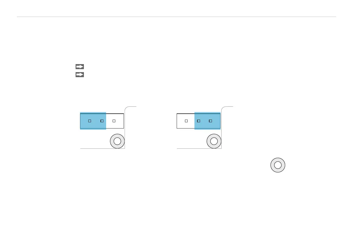
At the bottom side of the main board PCB you will find a connector (jumper), which has been placed from
factory side as shown in the picture (lower and middle pin connected), see Fig. 12. In this position the ground
connections (GND power supply/ outputs) are connected with the ground of the controller housing.
To avoid ground loops and related signal interferences in industrial environments it might be necessary to
interrupt this connection.
Remove the board by loosening the two screws in order to switch the jumper on the back of the board.
To do this, please put the jumper in the other position (middle and upper pin connected), see Fig. 13.
i
If the thermocouple is used, the ground connection GND - Housing should generally be interrupted.
Fig. 12 Plug connector (jumper),
GND to housing;
CT-SF, CT-CF, CTF, CTH, CTP models
Fig. 13 Plug connector (jumper),
GND - open;
CT-SF, CT-CF, CTF, CTH, CTP models
Position
cable gland

 Loading...


