Page 33
Electrical Installation
thermoMETER CT
7. Electrical Installation
7.1 Cable Connections
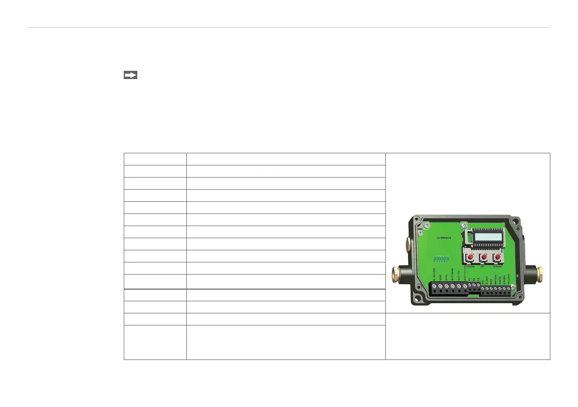
For the electrical installation of the thermoMETER CT, please open at first the cover of the controller
(4 screws).
Below the display are screw terminals for the cable connection.
7.1.1 Pin Assignment
7.1.1.1 CT-SF02, CT-SF15, CT-SF22, CTF-SF15, CTF-SF25, CTH-SF02, CTH-SF10, CTP-7 and CTP-3
Models
PIN Designation
+8 ... 36 VDC Power supply
GND Ground (0 V) of power supply
GND Ground (0 V) of internal in- and outputs
OUT-AMB Analog output sensor temperature (mV)
OUT-TC Analog output thermocouple (J or K)
OUT-mV/mA Analog output object temperature (mV or mA)
F1-F3 Functional inputs
AL2 Alarm 2 (Open-collector output)
3V SW 3 VDC, switchable for laser sighting tool
GND Ground (o V), for laser sighting tool
BROWN Temperature probe sensor
WHITE Temperature probe sensor
GREEN Detector signal (-)
Fig. 7 Opened controller CT-SF02,
CT-SF15, CT-SF22 / CTP-7 / CTF-SF15,
CTF-SF25, CTH-SF02, CTH-SF10 with
terminal connections
YELLOW Detector signal (+)

 Loading...


