15
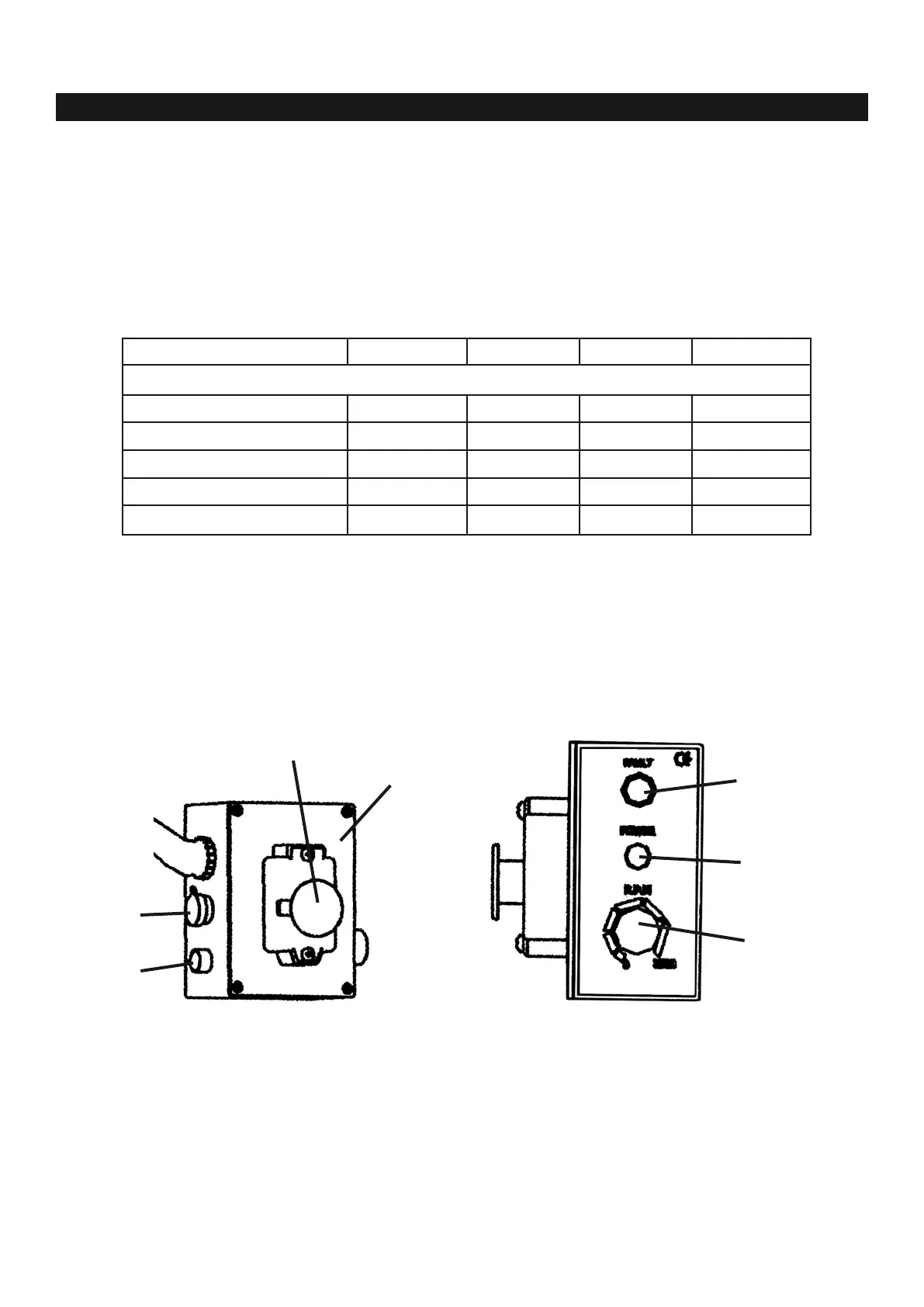
A. Emergency stop switch
B. Electric control box
C. Digital readout socket
D. Fuse holder
E. Yellow lamp
F. Green lamp
G. Variable speed control knob
7.1 Power Connection/Disconnection & Operation
(1) The connection, disconnection and grounding is carried out through the plug, equipped on the machine.
For safety reasons, do not change this plug into any other type under any circumstances.
(2) For the protection of control device, we recommend the operator to supply a fuse with a current rating
and the total length between fuse and connection terminal according to the following Extension Lead
Chart.
(3) The exact power source is 120v, single phase, 60Hz.
(4) Make sure the Emergency Stop switch (A) (left on the control box) is in closed position before
plugging in cord.
(5) Disconnect tools from power source with plug before servicing and when changing accessories
such as guard.
Ampere Rating 3A 6A 10A 13A
7.5m 0.75 0.75 1.0 1.25
15m 0.75 0.75 1.0 1.5
22.5m 0.75 0.75 1.0 1.5
30m 0.75 0.75 1.25 1.5
45.5m 0.75 1.25 1.5 2.5
Extension Cable Length Wire Size mm
2
EXTENSION LEAD CHART
CHAPTER 7 • POWER CONNECTIONS & ELECTRICITY
A
B
C
D
E
F
G