Hazardous area
inductance
The inductance (Li) of the meter is 0.0 μH. This value plus the field
wiring inductance (Lcable), must be lower than the maximum
allowable inductance (La) specified by the safety barrier. The
following equation can then be used to calculate the maximum cable
length between the meter and the barrier: Li + Lcable ≤ La
3.3.2 Wire all intrinsically safe using safety barriers
Micro Motion provides a safety barrier installation kit for wiring the meter in a hazardous
area. Contact your local sales representative or Micro Motion Customer Support at
flow.support@emerson.com for more information on ordering a barrier kit.
CAUTION!
• Meter installation and wiring should be performed by suitably trained personnel only in
accordance with the applicable code of practice.
• Refer to the hazardous area approvals documentation shipped with your meter. Safety
instructions are available on the Micro Motion Product Documentation DVD and
accessible on the Micro Motion website at www.micromotion.com.
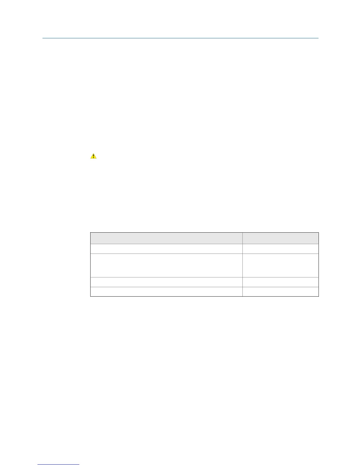
The safety barrier kit provides barriers for connecting all of the available meter outputs.
Use the provided barriers with the designated output.
Output(s) Barrier
4–20 mA MTL7728P+
• 4–20 mA
• Time Period Signal (TPS)
• Discrete
MTL7728P+
Modbus/RS-485 MTL7761AC
Power MTL7728P+
Procedure
Wire the barriers to the appropriate output terminal and pins (see Figure 3-3).
Wiring
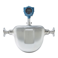
22 Micro Motion Compact Density Meter