Minimum wire area (mm
2
per meter)Figure 1-12:
0.000
0.050
0.100
0.150
0.200
0.250
0.300
0.350
0.400
0.450
0.500
0.550
0.600
0.650
0.700
0.750
0.800
0.850
0.900
100 200 300 400 500 600 700 800 900 1000
Minimum Wire Area (mm
2
)
Distance of Installation (m)
Minimum Wire Area (mm
2
)
22.8V
24V
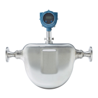
1.5 Perform a pre-installation meter check
1. Remove the meter from the box.
CAUTION!
Handle the meter with care. Follow all corporate, local, and national safety regulations
for lifting and moving the meter.
2. Visually inspect the meter for any physical damage.
If you notice any physical damage to the meter, immediately contact Micro Motion
Customer Support at flow.support@emerson.com.
3. Position and secure the meter in a vertical position with the flow arrow pointing
upward.
4. Connect the power wiring, and power up the meter.
Remove the back transmitter housing cover to access the PWR terminals.
Planning
Installation Manual 9