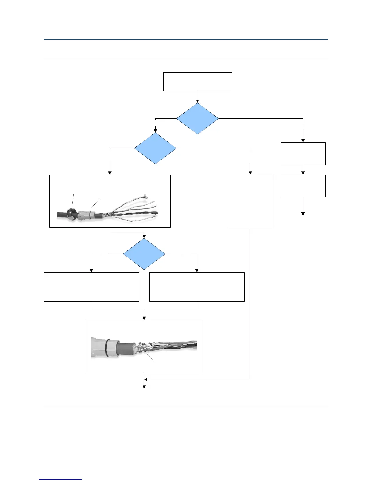
4-wire cable preparationFigure 3-7:
Cable layout
Run conduit to
sensor
Metal conduit
Wrap the drain wires twice around the shield and cut off
the excess drain wires.
Micro Motion
cable gland
Pass the wires
through the gland.
Terminate the drain
wires inside the
gland.
Cable glands
Remove the integral processor
cover
Go to the shielding
procedure
Done
(do not perform the
shielding procedure)
Gland supplier
User-supplied
cable gland
Lay cable in conduit
Drain wires
wrapped around
shield
Gland type
Pass the wires through the gland nut and clamping insert.
Clamping
insert
Gland nut
1. Strip 4-1/2 inch (115 mm) of cable jacket.
2. Remove the clear wrap and filler material.
3. Strip all but 3/4 inch (19 mm) of shielding.
1. Strip 4-1/4 inch (108 mm) of cable jacket.
2. Remove the clear wrap and filler material.
3. Strip all but 1/2 inch (12 mm) of shielding.
NPT
M20
Wiring
30 Micro Motion Compact Density Meter