1. Hardware Description
1.1 Schematic and Key Features
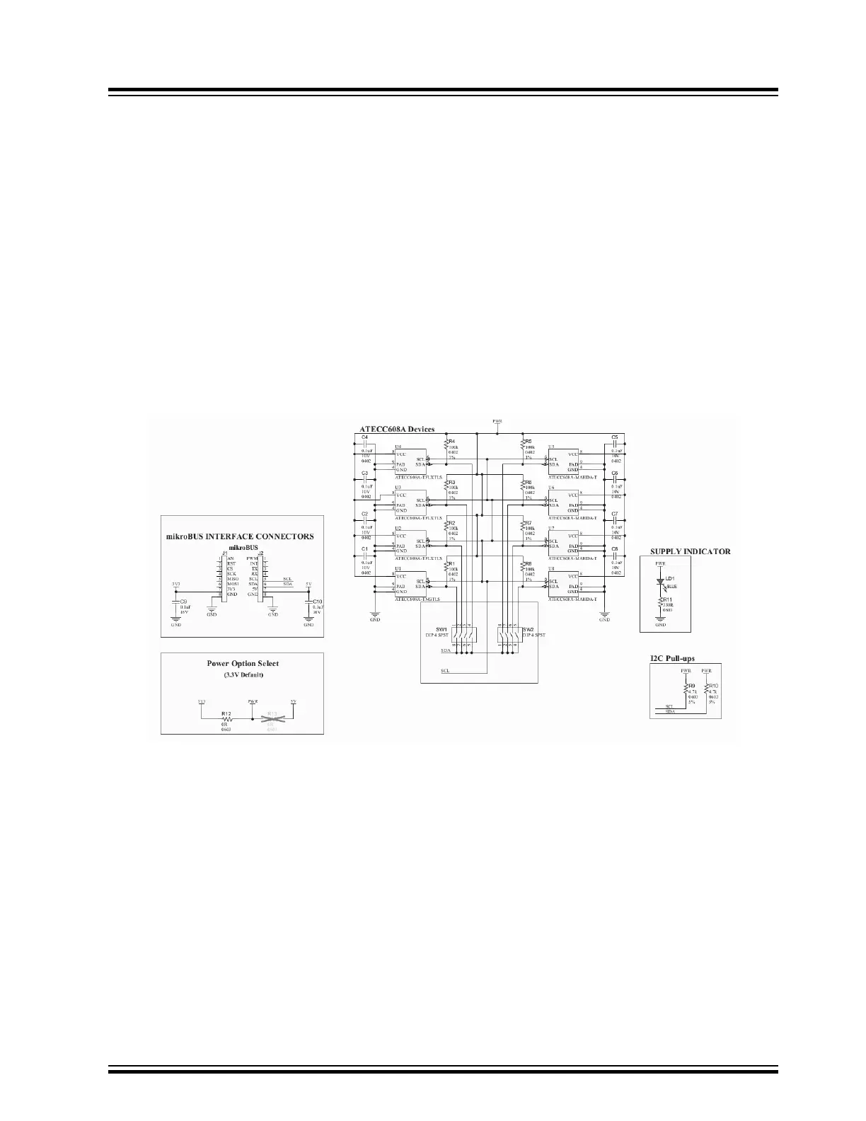
• One ATECC608A-TNGTLS Trust&GO Device (U1)
• Three ATECC608A-TFLXTLS Prototype TrustFLEX Devices (U2, U3, U4)
• Four ATECC608A-MAHDA TrustCUSTOM Devices (U5, U6, U7, U8)
• Two 4-Position SPST DIP Switches for Device Selection (SW1, SW2)
• One mikroBUS Connector (J1, J2)
• On-Board 4.7k I
2
C Pull-Up Resistors (R9, R10)
• On-Board LED Power Indicator (LD1)
• Zero-Ohm Resistor Jumpers to Select a 3.3V or 5V Power (3.3V Enabled by Default via R12)
Note: To enable a 5V power, remove R12 and solder a zero-ohm resistor into R11.
Figure 1-1. ATECC608A Trust Development Board Schematic
1.2 Device Selection
Devices Hardware Selection
Each secure element has a switch connection that enables the user to select a given device. Slide the DIP switch to
the ON state to enable the device selection. Selecting the device connects the corresponding SDA line through the
DIP switch. The SCL signals of all eight devices are connected together. A large value pull-up resistor on each SDA
line of each device keeps the device in a low-current state when not selected. Note that the switch number shown on
the top of the board (not the number on the switch) corresponds to the device identifier U# on the back of the
board.
DT100104
Hardware Description
© 2019 Microchip Technology Inc.
User Guide
DS50002922A-page 3