MCP2515 CAN Bus Monitor Demo Board User’s Guide
DS50001757B-page 14 2008-2014 Microchip Technology Inc.
2.3 GETTING STARTED
The MCP2515 CAN Bus Monitor Demo Board is a fully functional, assembled, and
tested kit used to demonstrate the MCP2515 in a CAN bus environment. The following
describes the basic setup and operation. See Figure 2-1 and Figure 2-2 for a simplified
functional diagram and block diagram.
1. Connect the two boards together using the cable.
2. Connect the USB cable to PC.
3. The TX LED (D2) on both boards will blink for about two seconds to indicate the
Power-on Reset de-bounce routine executed by the microcontroller. D9 LED will
remain ON to indicate the monitoring board is ready.
4. Start the bus monitor software. Both boards will be configured to 125 kbps CAN
rate by default. Select Device > Connect
to connect the board to the GUI.
5. Traffic can now be generated by pressing the LOAD button on the traffic
generator board.
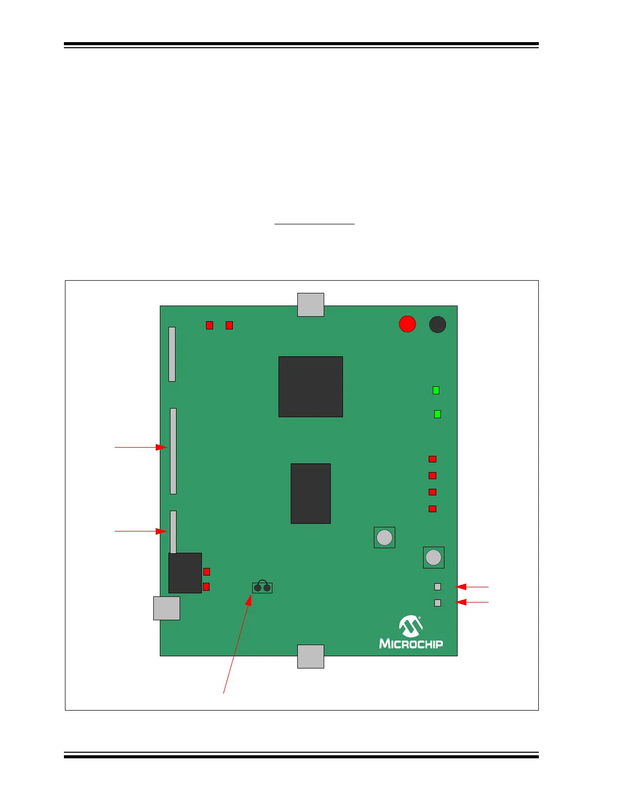
FIGURE 2-1: BLOCK DIAGRAM
0&3
3,&)
ICSP HEADER
GND
RESET
POWER
USB
USB
EXT
0&3
CAN
USB
CAN (ALT)
+5V from
CAN cable
Bus Loading (%)
25
50 75 100
CAN
(default)
+5V
TX
RX
LOAD
H
L
Bus Test
Points
TX/RX
Header
Serial and
INT Pins
Header
Jumpers: Shorted by
default on PCB bottom