EasyManua.ls Logo

Microgate SyncLink - General Purpose I;O Signals

Default Icon
13 pages
Print Icon
To Next Page IconTo Next Page
To Previous Page IconTo Previous Page
Loading...
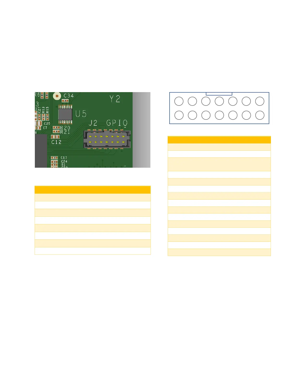
General Purpose I/O Signals
A 14 pin header (J2, Molex PN 87832-1420) provides 12 general purpose input/output signals (GPIO[0]
to GPIO[11]) for application specific use. Applications configure, control and monitor these signals with
the serial API. Each signal may be configured as an input (power on default) or output. GPIO signals are
3.3V TTL compatible and inputs are 5V tolerant. Exceeding specifications can damage the card.
GPIO Pin Assignments
Pin
Description
1
Ground
2
GCK0 Dedicated special purpose
LVTTL input Leave unconnected
3
GPIO[6]
4
GPIO[0]
5
GPIO[7]
6
GPIO[1]
7
GPIO[8]
8
GPIO[2]
9
GPIO[9]
10
GPIO[3]
11
GPIO[10]
12
GPIO[4]
13
GPIO[11]
14
GPIO[5]
GPIO DC Specifications
Name
Min
Max
V
IL
(input low)
-0.5V
0.8V
V
IH
(input high)
2.0V
5.5V
I
IN
(input current)
+/-10uA
V
OL
(output low)
0.4V
V
OH
(output high)
2.4V
I
OL
(output low)
24mA
I
OH
(output high)
-24mA
13
1
5
3
7
11
9
14
2
6
4
8
12
10

Related product manuals