Clock Polarity
Synchronous serial communications (HDLC/Bisync/Monosync) may use separate clock signals to control
the timing of data signals. One clock cycle equals one bit. There are two clock edges (rising and falling)
for each clock cycle. On one edge, the transmit data output changes. On the other edge, the receive
data input is sampled. The assignment of clock edges to transmit data transition and receive data
sampling is referred to as clock polarity.
SyncLink clock polarity is compatible with RS-232/RS-422/V.24/V.28/V.11:
RS-232/V.28 Single Ended Signals
• +3V to +15V (+5V typical) = clock on
• -3V to -15V (-5V typical) = clock off
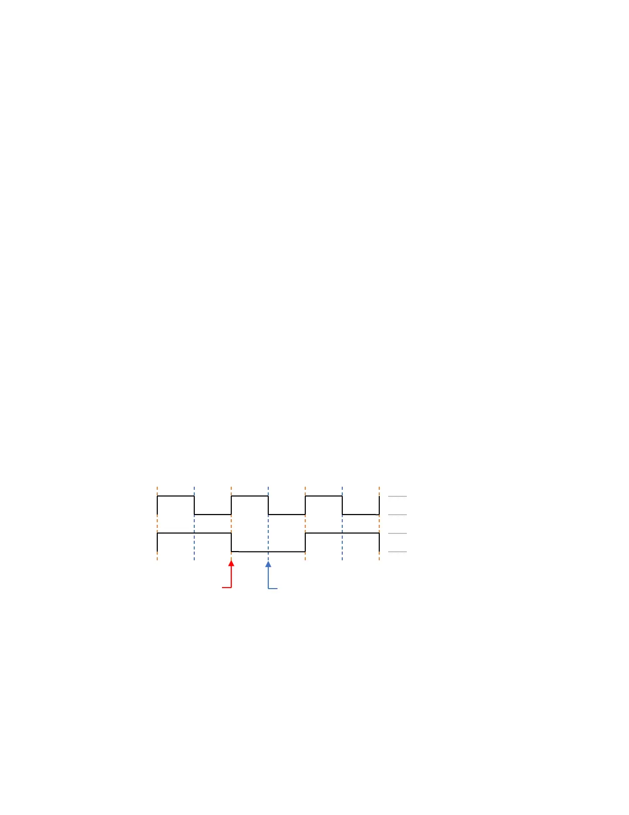
• On to Off edge (falling edge) = receive data sample (bit center)
• Off to On edge (rising edge) = transmit data transition (bit edge)
RS-422/RS-485/V.11 Differential Signals
• +200mV to +6V (+2V typical) = clock on
• -200mV to -6V (-2V typical) = clock off
• On to Off edge (falling edge) = receive data sample (bit center)
• Off to On edge (rising edge) = transmit data transition (bit edge)
Most serial communications equipment uses the above clock polarity, but some non-standard
equipment may use the opposite polarity. For differential signals, inverting the conductors of each clock
signal pair will alter the polarity.