EasyManua.ls Logo

Microgate SyncLink - V.35

Default Icon
13 pages
Print Icon
To Next Page IconTo Next Page
To Previous Page IconTo Previous Page
Loading...
V.35
V.35 uses both single ended and differential signals on a 34-pin block connector. To use this standard,
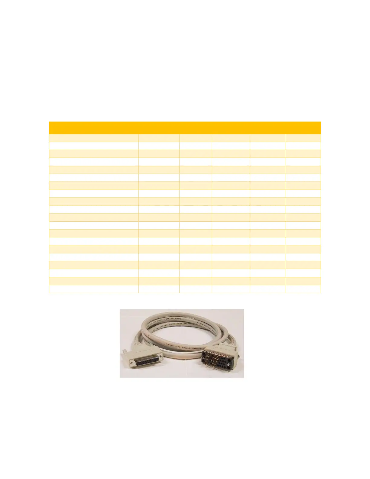
select the V.35 interface type and use the MicroGate V.35 cable (Part # 2534GT, picture shown below).
LL, RL, and RI signals are available on the HD-26 and DB-25 connectors but are not available (NC = no
connect) on the 34-pin block connector when using the V.35 cable.
Maximum data rate is 10Mbps. Cable length and signal loading may reduce the maximum data rate.
V.35 Male DTE
Signal
Electrical
HD-26 Pin
DB-25 Pin
V.35 Pin
Direction
TxD (-/A), Transmit Data
RS-422/V.11
8
2
P
Output
RxD (-/A), Receive Data
RS-422/V.11
17
3
R
Input
RTS, Request to Send
RS-232/V.28
1
4
C
Output
CTS, Clear to Send
RS-232/V.28
24
5
D
Input
DSR, Data Set Ready
RS-232/V.28
19
6
E
Input
Signal Ground
14
7
B
DCD, Data Carrier Detect
RS-232/V.28
22
8
F
Input
RxC (+/B), Receive Clock
RS-422/V.11
11
9
X
Input
AuxClk (+/B), DTE Clock Output
RS-422/V.11
7
11
W
Output
TxC (+/B), Transmit Clock
RS-422/V.11
26
12
AA
Input
TxD (+/B), Transmit Data
RS-422/V.11
9
14
S
Output
TxC (-/A), Transmit Clock
RS-422/V.11
25
15
Y
Input
RxD (+/B), Receive Data
RS-422/V.11
18
16
T
Input
RxC (-/A), Receive Clock
RS-422/V.11
10
17
V
Input
LL, Local Loopback Control
RS-232/V.28
13
18
NC
Output
DTR, Data Terminal Ready
RS-232/V.28
3
20
H
Output
RL, Remote Loopback Control
RS-232/V.28
12
21
NC
Output
RI, Ring Indicator
RS-232/V.28
20
22
NC
Input
AuxClk (-/A), DTE Clock Output
RS-422/V.11
6
24
24
Output
V.35 Cable (Part# 2534GT)

Related product manuals