11
Torex Power Management Board Components
Two 3-pin receptacles are used to connect the Power Management Board to the AC Power Cell.
The resulting DC output voltage can be accessed via connector P7 or P8. Additional headers are
provided for connecting to other accessory boards and/or for powering a device with energy
harvesting.
Toggle in/out Onboard Capacitors
Table 6: Board Pinout
Connecting Power Management to AC Power Cell
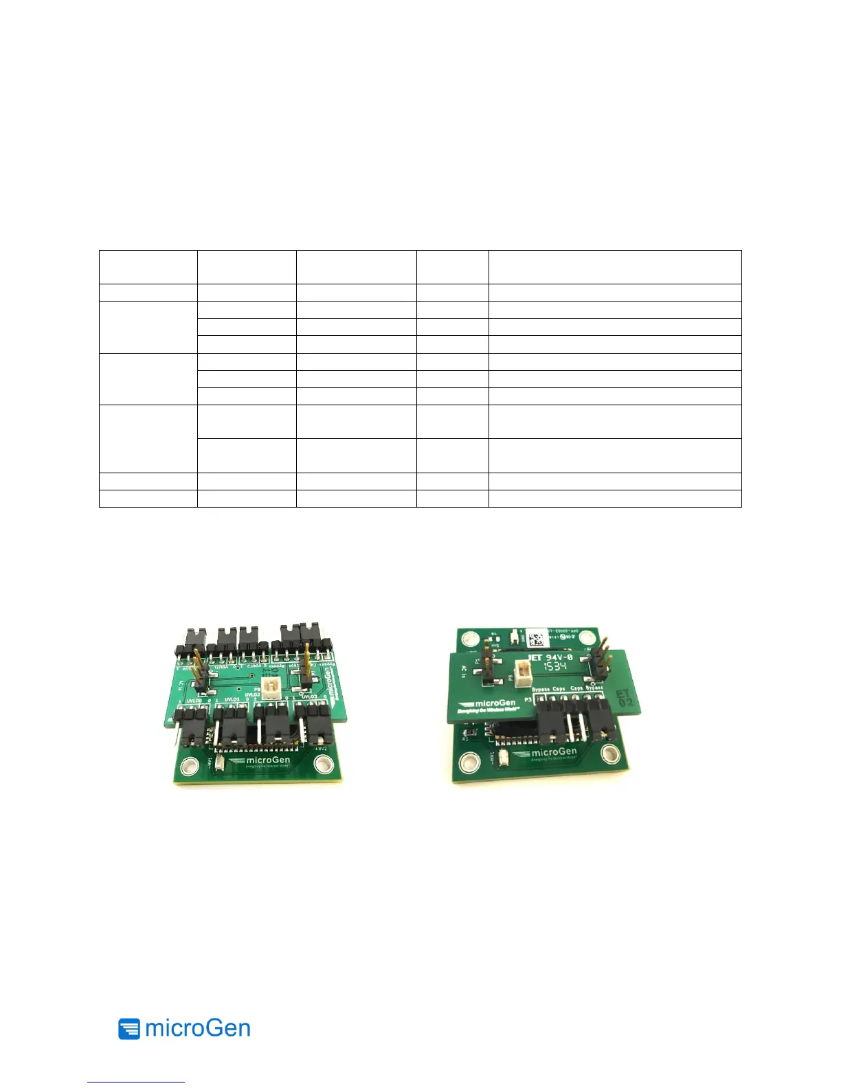
To properly connect the AC Power cell to one of the Power Management Boards P2 on the Power
Management Board must align with P1 on the AC Power Cell. Figures 5 and 6 show the correct
orientation of the boards. Please note the microGen logo in each picture and how they align
differently on the two Power Management Boards.
Figure 5: LTC3330 and AC Power Cell
Figure 6: Torex LDO and AC Power Cell